


Rotary SI/CI Combustion Engines: A Thing of the Future?
The internal combustion engine enjoys widespread use as an inexpensive and reliable power conversion system. While piston engines date back 150 years, various alternative engine architectures and cycles have been considered.

Today’s small piston engines can be inexpensive, and have suitable reliability to serve a variety of applications including scooters, motorcycles, ATVs, boats, lawn and garden equipment, and auxiliary power generation, not to mention small aircraft including UAVs. While piston engines enjoy prolific use, their efficiency is remarkably low.
The Wankel rotary engine has some advantages that make it a formidable contender for some markets served by reciprocating engines. The piston in a four-stroke reciprocating engine momentarily comes to rest four times per cycle as its direction of motion changes. In contrast, the moving parts in a rotary engine are in continuous unidirectional rotational motion. However, the rotary type engine has some drawbacks, including fuel economy.

Connecticut-based LiquidPiston has under development several new engine architectures, with a focus on rotary engines that share some aspects of the Wankel-type engine. A primary motivation for development of the new architecture is the ability to embody an optimized four-stroke cycle, dubbed the high-efficiency hybrid cycle (HEHC), which can change fundamentally the operation of internal-combustion engines.
The X engine platform developed by LiquidPiston is simple, and has no reciprocating parts — features common to the conventional rotary engines. However, in contrast, the X engine has a higher compression ratio (CR), and a stationary conical/spherical combustion chamber suitable for direct injection (DI) and compression ignition (CI). LiquidPiston has developed initial prototypes to demonstrate the principles of the engine, including the X1 and the XMv3.
Basics of high-efficiency hybrid cycle
As the name implies, the HEHC attempts to combine (hybridize) the best features of several thermodynamic cycles for increased efficiency. In its purest form, the HEHC combines the high CR of the diesel cycle; the constant-volume (isochoric) combustion of the Otto cycle, achieved by long-duration burn, through a dwell in volume near top dead center (TDC); and overexpansion to atmospheric pressure via the Atkinson cycle.
The X architecture is designed to accomplish this cycle. In the CI version of the HEHC cycle, fresh air (without fuel) is compressed to a high CR in a chamber of the engine. Fuel is injected into the combustion chamber just prior to TDC and CI takes place.
The majority of combustion occurs under a relatively constant-volume condition, achieved by having a long-duration dwell in combustion chamber volume near TDC. The combustion gas then expands to a larger volume than the initial intake volume.

The HEHC cycle can also operate with SI, albeit with lower resulting efficiencies. In this case an air-fuel mixture is compressed to a lower CR, similar to standard Otto cycle engines. The reduction in CR causes a reduction in efficiency compared to CI, but the dwell in combustion volume near TDC results in higher peak pressure and efficiency than piston engines operating with SI. This is related to the slower variation of displacement in proximity to TDC than piston engines.
Overexpansion further increases efficiency, similar to the Atkinson cycle. The dwell-in volume at TDC allows the engine to more closely achieve true constant-volume combustion (isochoric head addition), compared to a piston implementation of the Otto cycle.
Engine structure and operation
A single-rotor X engine consists of a rotor, housing, eccentric shaft, counter balance weight, and intake/exhaust side plates and/or covers. It has a simple layout, with only two rotating parts. The 70-hp (52-kW) X1 architecture operates on CI. The smaller engine of the family, the 3-hp (2.2-kW) XMv3, which operates on the modified HEHC cycle for SI operation, is a scaled-down version of the X1. The operating principles and components of this engine are nearly the same.
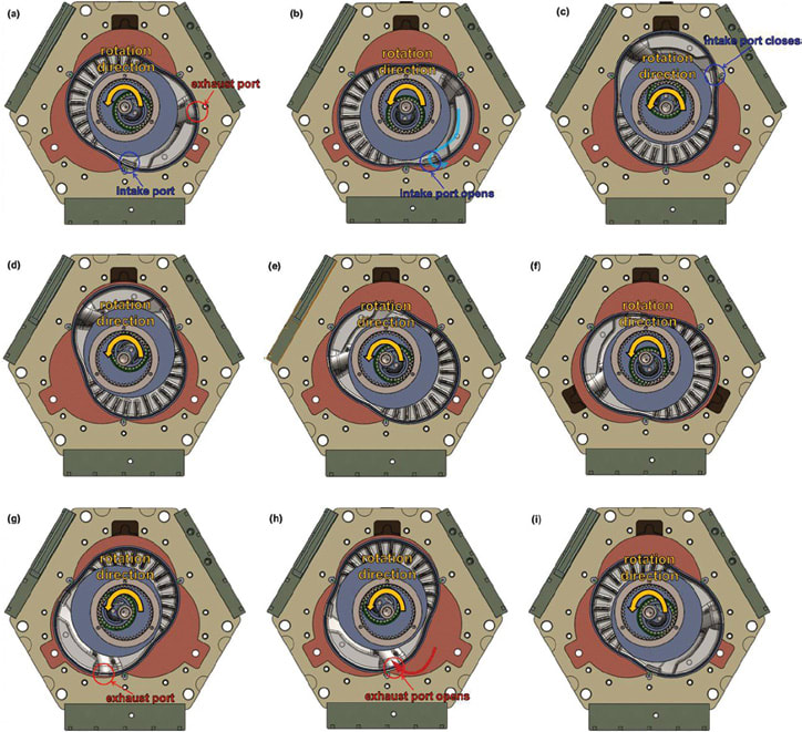
The housing and rotor form three working chambers within the engine. Each of these chambers successively compresses and expands as the rotor turns within it. A four-stroke cycle is completed within each of the three chambers, simultaneously. The processes includes intake, compression, combustion and expansion, and exhaust.

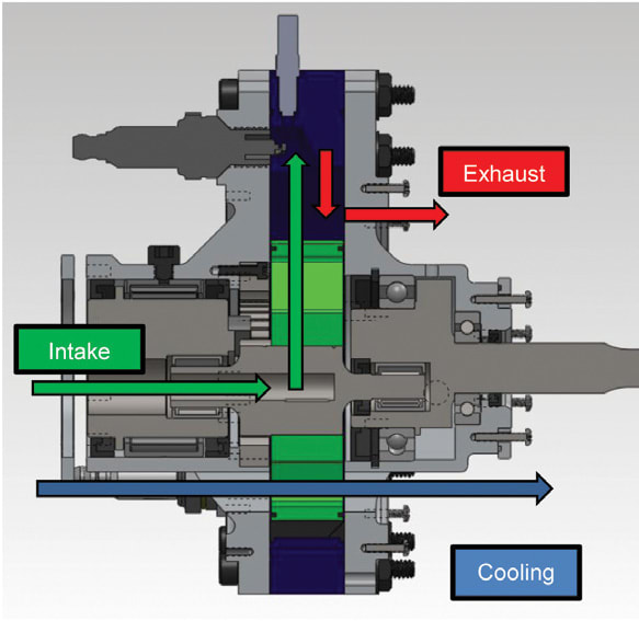
Intake and exhaust: The intake plate has three windows. Fresh air flows axially from the intake manifold, through the window. At least one of the three windows is always engaged with the intake channel within the rotor. Thus, the intake channel of the rotor is constantly supplied with fresh air from the intake manifold.
The intake channel is allowed to flow gas to one of the working chambers through a port on the radial surface of the rotor. As the rotor turns, the port is moving, and is only exposed to one of the chambers at a given time. When the intake process starts, the intake port of the rotor is first exposed to a given chamber when its volume is minimal.

The location of the intake port determines the opening and closing timing of the intake. By locating the intake port so that it either closes early or late, the final intake volume will be smaller than the maximum expansion volume of the chamber, so this simple geometric change can be used to achieve overexpansion in the engine.
The exhaust process is similar to the intake process, but happens in reverse. The exhaust plate has three windows that allow axial flow of exhaust from an exhaust channel in the rotor to flow to the exhaust manifold, eventually exiting the engine.
At all times, at least one of the three windows is engaged with the exhaust channel in the rotor, allowing unobstructed flow.
Following the expansion process within the chamber, as the rotor turns, an exhaust port on the radial surface of the rotor opens to the chamber. The port opens when volume is greatest. The rotor motion causes the volume to decrease, thereby causing a flow of exhaust gasses from the chamber, through the exhaust port in the rotor, through the exhaust channel in the rotor, and finally to the exhaust manifold as the gas passes through the exhaust plate windows.
Compression & combustion and expansion: Following the intake stroke, when the intake port of the rotor closes in one of the working chambers, the rotor motion will cause the volume in the chamber to decrease, causing compression of the gas.
Eventually, at TDC, the working chamber volume will reach a minimum, and most of the gas is displaced into a constant-volume combustion chamber, which is essentially a recess within the housing. A high CR is achieved by having a small combustion chamber.
The compression phase is followed by combustion and expansion. When the rotor approaches TDC, in X1, fuel is injected using a high-pressure common-rail fuel-injection system. For LiquidPiston’s prototype development, it utilized off-the-shelf Bosch pumps and injectors. Near TDC, the arc of the housing matches the arc of the rotor, and the volume remains approximately constant over ~20° of rotor rotation.

During this period, most of the gas is in the combustion chamber. There is plenty of time to inject fuel, and the engine can mix and burn a majority of the fuel under constant-volume conditions, before the expansion begins.
In the XMv3 engine, the fuel and air is premixed, and a lower CR is utilized with SI. The engine is still expected to benefit from the long-duration constant-volume combustion process.
Finally, as the rotor continues turning, the volume is expanded. The gas pressure pushes on the rotor, which translates to brake torque. The expansion process continues until the maximal expansion volume is reached, and the exhaust port of the rotor opens.
If the intake and exhaust ports are asymmetrically located, the effective expansion ratio can be significantly higher than the CR, allowing more energy of the gas to be converted into useful work. This overexpansion also has the effect of lowering average temperature in the chamber, reducing cooling needs. Additionally, the exhaust pressure can be near atmospheric — offering lower temperatures and pressures than traditional engine exhaust.
Sealing and cooling: The rotor seals in rotary engines perform the same duties as the piston rings in a reciprocating engine because they provide a seal for the combustion gases. These consist of a face seal on each side of the rotor, three apex seals, and stationary O-rings in the housing.
Face seals are installed into the grooves on the rotor face with springs. Two-piece apex seals are used in the X1 engine for better gas sealing performance compared to one-piece apex seals. While dimensionally different, the seals are similar to Mazda RX-8 seals.
The gas seals are initially loaded with spring force, but in operation, the gas forces acting on the seals far exceed the spring forces. Since apex seals of a conventional rotary engine are inserted in radial slots at each rotor apex, the significant portion of the force that works on the apex seal is centrifugal force, which is one of the major constraints for designing apex seals in conventional rotary engines.
However, there is no centrifugal force on apex seals of the X1 engine because the apex seals are inserted at the housing, which is a stationary part. This also changes the lubrication strategy, as stationary apex seals can be lubricated with a small quantity of oil metered directly at the seal location through the stationary main housing or side housings.
The overexpansion process of HEHC reduces the average cylinder temperature, and the exhaust is cooler. On the other hand, higher combustion temperatures are reached during constant-volume combustion. It should be noted that even with constant-volume combustion, peak temperatures and pressures in the naturally aspirated HEHC case are lower than a turbocharged diesel engine. Cooling is necessary to prevent over-heating of components and premature wear, especially due to degradation of the oil film at the seal interfaces.
Unlike the Wankel-type engine, combustion is spread across three chambers of the housing, and each of these chambers also sees a cool intake stroke, so heating issues of the housing are expected to be less than heating issues of the rotor.
Traditional cooling strategies — for example, a water jacket in the housing and oil cooling via passages in the rotor — can be utilized. The initial X1 prototype was run without any cooling, as this prototype was designed only to demonstrate the basic operation of the cycle. The XMv3 engine utilizes an air cooling strategy, with air blown axially through the rotor across a plurality of ribs.
Differences from Wankel
The X engine shares some advantages of the rotary engine architecture similar to the Wankel, for example the simplicity of having two major moving parts; the low-vibration/purely balanced rotor; and the advantage of not having any oscillating masses, thereby reducing need for a flywheel and making the engine more responsive. However, there are significant differences as well.
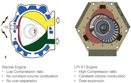
The thermodynamic cycle of the Wankel engine is the Otto cycle, but the implementation is inferior to the traditional piston engine. The X engine, on the other hand, is optimized to work on the HEHC cycle with the advantages of that cycle, either CI or SI.
The X engine compresses all of the gas into an isolated combustion chamber. This combustion chamber can be small, leading to a higher CR than is possible with the Wankel engine.
Also, the isolated combustion chamber can have an approximately spherical geometry — e.g., it will have a low surface area-to-volume ratio. Given that engines lose a large part of their heat during the combustion process, the X engine will have a favorable surface area during this part of the cycle, leading to less heat transfer losses. During the expansion, the surface area could be greater than a regular piston engine with higher heat loss, but the majority of heat transfer takes place during the combustion and the beginning of the expansion stroke.
Lastly, the X engine, operating like an inverted-Wankel engine, has apex seals that are stationary in the housing, whereas the apex seals in the Wankel engine are in the rotor. Thus, the X engine does not have centrifugal loading of the seals and allows direct metering of lubrication to the seals. This approach has been demonstrated in the lab to significantly reduce wear of the engine, while supplying 10 times less oil to the engine compared to Wankel engines.
This article is based on SAE technical paper 2014-32-0104 by Alexander Shkolnik, Daniele Littera, Mark Nickerson, and Nikolay Shkolnik, LiquidPiston; and Kukwon Cho, Aramco Services Co.
More From SAE Media Group
Off-Highway Engineering
Navistar Updates A26 Engine, Improves FE by 4%
Automotive Engineering
Balancing GDI Fuel Economy and Emissions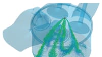
Off-Highway Engineering
Cummins Unveils New B7.2 Diesel Engine
Off-Highway Engineering
Westport Awarded LNG Development Program
Off-Highway Engineering
Could This Infinitely Variable Compression Mechanism Be the Next Piston Engine Game-Changer?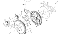
Automotive Engineering
Mazda Plots Wankel-powered Range Extenders, HCCI Mild Hybrids
Off-Highway Engineering
Mahle, Liebherr Develop Active Pre-Chamber for Hydrogen ICE
Off-Highway Engineering
SwRI Rolls out Hydrogen Demonstration Truck
Off-Highway Engineering
Cummins New X15 Engine Meets Upcoming Regs While Boosting Efficiency
Automotive Engineering
Cooled EGR Shows Benefits for Gasoline Engines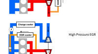
Automotive Engineering
Porsche Unveils New Downsized, Boosted 3.0-L Boxer Six
Off-Highway Engineering
Off-highway Calibration Challenges — Big and Complex
Automotive Engineering
2015 Engines Ride a Technology Tidal Wave
Automotive Engineering
'Reman' Engine Market Steady, but Complexity Challenges Production Efficiency
Automotive Engineering
Achates Aims at 2025 Light-truck Power
Off-Highway Engineering
Cummins’ X15 Is a Model of Design Efficiency
Automotive Engineering
Extending a Wankel Future on Hydrogen Fuel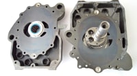
Automotive Engineering
How Higher-Quality Gasoline Keeps Modern Engines Clean and Efficient
Automotive Engineering
Spark of Genius
Tech Briefs
Electrohydraulically Actuated Valve Train
Tech Briefs INSIDER
Replacing Camshafts with Valves Paves Way for Cheaper, Greener Engines
Automotive Engineering
New Engines 2016
Automotive Engineering
Future ICEs: What Comes After 2025?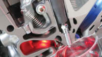
Off-Highway Engineering
Development Trends for Heavy Engines
Off-Highway Engineering
Scania Adapts On-Highway Diesel for New Off-Highway Engine Platform
Automotive Engineering
Targeting 40% BTE with Advanced VCR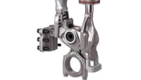
Automotive Engineering
Mahle’s Pre-Chamber MJI Technology Is Sparking Ignition Advances
Automotive Engineering
New Axial-Piston Engine Aimed at Range Extenders, Military Applications
Automotive Engineering
Audi's New V6 Diesel to Feature Electric Turbocharging, New NOx Technology
Off-Highway Engineering
The Complicated Future of Off-Highway Engines
Top Stories
NewsSensors/Data Acquisition
![]() Microvision Aquires Luminar, Plans Relationship Restoration, Multi-industry Push
Microvision Aquires Luminar, Plans Relationship Restoration, Multi-industry Push
INSIDERRF & Microwave Electronics
![]() A Next Generation Helmet System for Navy Pilots
A Next Generation Helmet System for Navy Pilots
INSIDERWeapons Systems
![]() New Raytheon and Lockheed Martin Agreements Expand Missile Defense Production
New Raytheon and Lockheed Martin Agreements Expand Missile Defense Production
NewsAutomotive
![]() Ford Announces 48-Volt Architecture for Future Electric Truck
Ford Announces 48-Volt Architecture for Future Electric Truck
INSIDERAerospace
![]() Active Strake System Cuts Cruise Drag, Boosts Flight Efficiency
Active Strake System Cuts Cruise Drag, Boosts Flight Efficiency
ArticlesTransportation
Webcasts
Aerospace
![]() Cooling a New Generation of Aerospace and Defense Embedded...
Cooling a New Generation of Aerospace and Defense Embedded...
Energy
![]() Battery Abuse Testing: Pushing to Failure
Battery Abuse Testing: Pushing to Failure
Power
![]() A FREE Two-Day Event Dedicated to Connected Mobility
A FREE Two-Day Event Dedicated to Connected Mobility
Automotive
![]() Quiet, Please: NVH Improvement Opportunities in the Early Design Cycle
Quiet, Please: NVH Improvement Opportunities in the Early Design Cycle
Electronics & Computers
![]() Advantages of Smart Power Distribution Unit Design for Automotive &...
Advantages of Smart Power Distribution Unit Design for Automotive &...
Unmanned Systems
![]() Sesame Solar's Nanogrid Tech Promises Major Gains in Drone Endurance
Sesame Solar's Nanogrid Tech Promises Major Gains in Drone Endurance