


Off-highway Calibration Challenges — Big and Complex
As the final set of Tier 4 regulations kick in for engines greater than 750 hp, calibration efforts must contend with complex engine and aftertreatment systems. Engine manufacturers and service providers deal with this complexity, but does it need to be so?
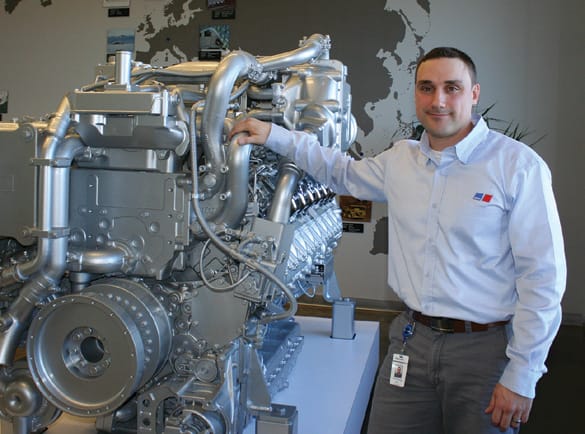
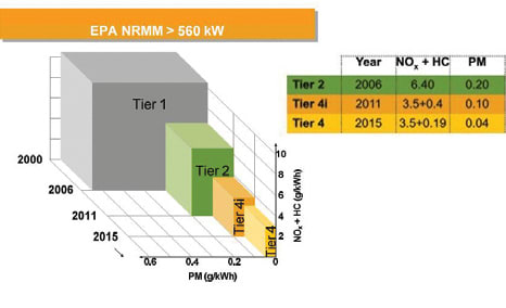
The U.S. EPA Tier 4 Final emissions regulations are set for final phase-in during calendar year 2015. This final phase-in period focuses on large engines, producing greater than 560 kW (750 hp). This is especially relevant to MTU, makers of some very large marine, rail, stationary, mining, and oil & gas engines. Some reach 10,000 kW (13,410 hp).
“We are not particularly worried about meeting the emissions regulations for this final phase-in period because we have been working toward this goal for a number of years,” explained Marc Schlichting, Manager of Application Engineering, Rail and Mining Engines for MTU America Inc.
The challenges that remain — as for most off-highway engine makers — are producing basic engine designs capable of meeting the needs of a broad range of applications. That means an engine design that powers oil extraction using hydraulic fracturing could also power U S. Coast Guard cutters or move rail locomotives.
Another demand is that all customers crave better fuel economy, requiring each new generation of engine to produce more with less than the one it replaces. This requires expertise to tune and calibrate each engine for its specific purpose, meeting sometimes conflicting requirements.
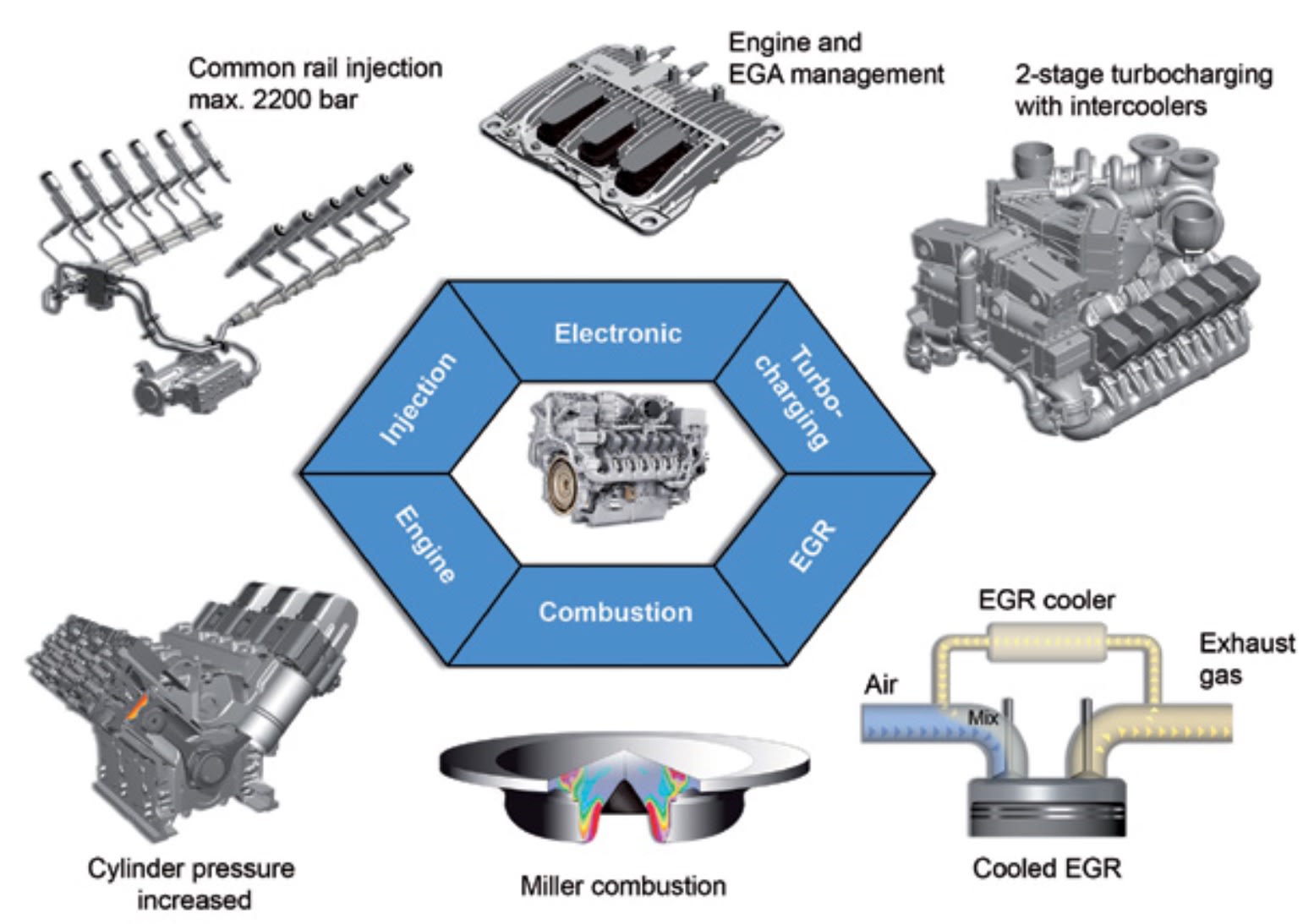
However, meeting the most stringent regulatory emissions requirements ever imposed — EPA Tier 4 — compounds that challenge. In response, MTU adopted advanced technology that makes for cleaner, efficient engines but increases complexity. In particular, they added six advanced technologies to each engine above 560 kW (750 hp), according to Schlichting.
These include: two-stage intercooled, regulated turbo-charging; cooled exhaust gas recirculation (EGR); low emissions combustion with Miller cycle; an advanced injection system; and increased peak cylinder pressures up to 215 bar (3120 psi) — all controlled by a new MTU-produced ADEC engine controller. Because of the size and uniqueness of their engines, they are in fact producers of specific engine components like turbochargers and fuel injection equipment that in other industries are purchased from suppliers.
However, the fact that they produce their own ECU coupled with a unique engine control strategy stands out.
ECU — and engine actions for emissions control
One way MTU leveraged this unique control strategy is in developing what they call “MTU smart injection.” A pressure sensor on each injector replaces exhaust temperature monitoring. These are monitored by an additional secondary control unit they term an Engine controller eXtension Unit (EXU.) This smart injection control system now continuously monitors pressure at each injector, enabling the ECU to adapt injection timing and duration.
One of the problems with direct-injection used in diesel compression-ignition engines is that squirting fuel into the chamber makes for a non-homogeneous charge. It varies from lean to rich throughout the cylinder, causing PM formation in rich pockets and other emissions headaches.
MTU’s common rail system, which can achieve 2500-bar (36-ksi) injection pressure, coupled with the injector sensors in closed-loop control allow for emissions stability under a variety of conditions. They claim to get closer-to-homogenous fuel combustion, achieving better fuel economy and lower emissions as a result. This builds on MTU’s existing injector equalization and calibration drift compensation techniques that ensures equal power distribution and stable emissions output from all cylinders at any load.
Another way they employ their ECU for emissions control is monitoring the air/fuel ratio (lambda) at the exhaust outlet using a standard O2 sensor, providing feedback to modulate EGR rates. “If you keep lambda at a constant level, the PM emissions will be nearly constant as a result,” explained Schlichting. “However, the peak level of PM emissions is primarily influenced by the hardware, such as injector tip or piston bowl.”
Aftertreatment ups the ante
Despite the success of companies like MTU in using various engine actions to mitigate emissions, aftertreatment devices like diesel particulate filters (DPFs), diesel oxidation catalysts (DOCs), and selective catalytic reduction (SCR) are also needed, either alone or in combination, to meet Tier 4 requirements, depending on the application.
“As we are ending the regulatory cycle with the final phase-in of Tier 4, the challenges now become the complexity of the aftertreatment,” said David Rodgers Commercial Director – Engines Business Unit of Ricardo. They provide a range of consultant services and powertrain software products.
The unit of Ricardo that Rodgers is in both provides tools and performs calibration and advice for the off-highway market, especially construction and agriculture equipment. This gives him a broader view of the problems of calibration in the industry. He also agrees that a common issue with any segment of off-highway is the large number of applications, engine platforms, engine ratings, and small take rates within an application.
“As certain markets become more niche, it is a little more difficult for [engine makers] to perform targeted validations for a specific market,” he said. Because of this, they might run into challenges with the aftertreatment not having been fully calibrated for all potential operating conditions.
“With complex aftertreatments, engineers need to manage all of the pre-heating and regeneration modes, along with diagnostics and operator alerts. This can lead to lack of proper heating of the aftertreatment devices or excessive regenerations because of the way inlet conditions were calibrated,” he said.
Calibrate smarter as complexity grows
One solution is simply more test and more calibration time. But that is reaching its practical limit as the number of parameters grows exponentially.
“To make their control systems more portable across a number of applications, engine makers and equipment OEMs are turning to model-based control systems,” said Rodgers. This means using a higher language, like MATLAB Simulink, to develop and validate a model and then use an auto-coding feature to create the actual code for the control software before calibration. This allows more reuse across applications and ratings, according to Rodgers.
Today, calibrations are not always filling out look-up tables with values or creating maps, according to him. He notes that there are predictive models for some simple, singular components that are becoming integral parts of calibrations.
“A good example is controlling EGR,” he said. “In most cases, you do not have direct measurement of exhaust gases. Controlling the EGR rate could use a look-up table of values, but we are finding that using models to predict exhaust gas and then using that output to set the EGR rate is better.”
He sees a steady evolution of more small models created for specific tasks, like the set point for EGR rate, used in conjunction with look-up tables and maps.
“Shortening the powertrain calibration process has become a major target for most companies,” agreed Yoann Bernard, Calibration Product Manager for D2T, a provider of engineering services and systems for calibration. “[It is a] costly task that requires hundreds of hours of test bench time,” a cost driven up by increasingly complex engines. Test and calibration time has grown from several days to several months, when testers account for the different regulations off-highway engine developers need to address along with Tier 4, such as European Union Stage IV.
He agrees that higher constrains on PM and hydrocarbon emissions has led to additional aftertreatment systems. “This leads to new challenges, but also to new potential for the whole system,” he said. To exploit these new possibilities, there are three avenues.
The first, according to him, is the use of advanced DOE techniques to tune the additional parameters. The second is taking into account the aftertreatment effect directly during the calibration process to get a better trade-off between fuel, urea consumption (used in SCR), and emissions by balancing in emissions engine-out and tail pipe aftertreatment. The final way is improving the aftertreatment efficiency by better matching the engine conditions like exhaust temperature.
Future challenges will be to reduce fuel consumption. “In that case, complex powertrains using partial hybridization, a heat recovery system, or turbo-compound could lead to even higher complexity,” he cautioned.
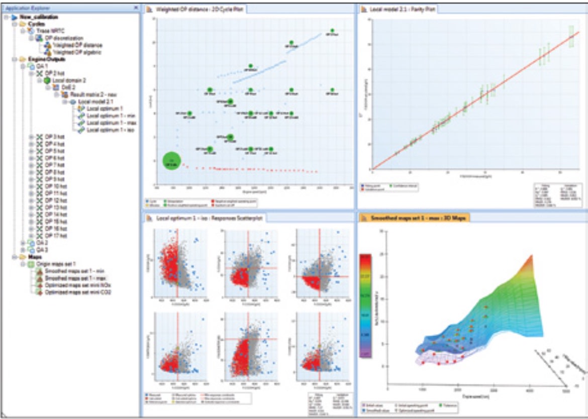
To help meet these challenges, D2T offers a number of products for use by calibrators. One of their newer ones they offer for ECU calibration is ICE2 (Integrated Calibration Environment for Internal Combustion Engines). “ICE2 provides innovative solutions based on DoE and model-based calibration techniques to perform powerful modeling and optimization,” he said, stating that these improvements result in 75% less calibration time.
There may be other reasons for complexity in control systems than complex engines and aftertreatment, according to Steve Haines, Owner of Optecon, an engine controls consulting company. His experience in the industry dates from when electronic controllers first became available on engines in the mid-1980s.
“One reason [for complex control systems] is because of time pressures. The easiest way to create a control system to start calibrating is to re-use algorithms from an earlier project. This means there is a huge amount of legacy software that is floating around — modified and adapted and added to in ways that make for less-than efficient code.”
He also believes the industry has evolved into distinct groups, one writing software and another group performing the calibrations.
“Communication between them is not so good and typically the software group does not understand engine systems as well as they might,” he said.
The result? Almost infinitely flexible control software with large numbers of look-up tables that need to be populated by calibrators. Flexible is good, but it makes for a complex system that takes longer to calibrate.
“Ideally, a control system should start with analysis of the actual engine, taking some of the tables out by developing more sophisticated controls,” he said. “But that comes from test analysis and an understanding of the engine, so those two groups need to work more closely — or even be the same people.
More From SAE Media Group
Off-Highway Engineering
The Complicated Future of Off-Highway Engines
Automotive Engineering
Balancing GDI Fuel Economy and Emissions
Off-Highway Engineering
Bigger Processors, Smaller Engines
Off-Highway Engineering
Mahle, Liebherr Develop Active Pre-Chamber for Hydrogen ICE
Automotive Engineering
Audi's New V6 Diesel to Feature Electric Turbocharging, New NOx Technology
Off-Highway Engineering
MTU Training Facility Helps Keep Complex Engines up and Running
Off-Highway Engineering
Downsizing a HD Diesel Engine for Off-Highway Applications
Automotive Engineering
Cooled EGR Shows Benefits for Gasoline Engines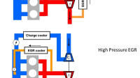
Off-Highway Engineering
Cummins Unveils New B7.2 Diesel Engine
Automotive Engineering
How Higher-Quality Gasoline Keeps Modern Engines Clean and Efficient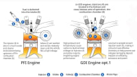
Off-Highway Engineering
Kohler Extends Its Hand in Off-Highway Diesels
Off-Highway Engineering
New Volvo D13 VGT Utilizes 24V Architecture
Off-Highway Engineering
Cummins’ New Mid-Displacement Turbos Quieter and More Efficient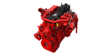
Off-Highway Engineering
Navistar Updates A26 Engine, Improves FE by 4%
Off-Highway Engineering
Westport Awarded LNG Development Program
Off-Highway Engineering
Enhanced Cat 3500 Engine Boosts Power 20%, Trims Fuel Usage by 10%
Off-Highway Engineering
Cummins in Production with 'Simplified' Tier 4 Final Engines
Off-Highway Engineering
Hatz's Next-Generation Industrial Compact Engine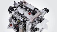
Off-Highway Engineering
Development Trends for Heavy Engines
Automotive Engineering
Delphi and Hyundai GDCI Program Aims to Top Diesel Efficiency
Automotive Engineering
Future ICEs: What Comes After 2025?
Automotive Engineering
Achates Aims at 2025 Light-truck Power
Off-Highway Engineering
Caterpillar Unveils New C13D Off-Highway Engine Platform
Off-Highway Engineering
AGCO Goes Clean and Green with CORE75 Engine
Automotive Engineering
Extending the ICE Age: Hyundai Optimizing Engines and Fuels
Automotive Engineering
Mahle’s Pre-Chamber MJI Technology Is Sparking Ignition Advances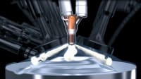
Tech Briefs
Making Diesel Engines Nearly Emission-Free
Off-Highway Engineering
Cummins New X15 Engine Meets Upcoming Regs While Boosting Efficiency
Off-Highway Engineering
Cummins Cylinder Deactivation Saves on Fuel and Emissions
Off-Highway Engineering
Iveco Pursues Natural Gas in Stralis NP Models
Top Stories
NewsSensors/Data Acquisition
![]() Microvision Aquires Luminar, Plans Relationship Restoration, Multi-industry Push
Microvision Aquires Luminar, Plans Relationship Restoration, Multi-industry Push
INSIDERRF & Microwave Electronics
![]() A Next Generation Helmet System for Navy Pilots
A Next Generation Helmet System for Navy Pilots
INSIDERWeapons Systems
![]() New Raytheon and Lockheed Martin Agreements Expand Missile Defense Production
New Raytheon and Lockheed Martin Agreements Expand Missile Defense Production
NewsAutomotive
![]() Ford Announces 48-Volt Architecture for Future Electric Truck
Ford Announces 48-Volt Architecture for Future Electric Truck
INSIDERAerospace
![]() Active Strake System Cuts Cruise Drag, Boosts Flight Efficiency
Active Strake System Cuts Cruise Drag, Boosts Flight Efficiency
ArticlesTransportation
Webcasts
Aerospace
![]() Cooling a New Generation of Aerospace and Defense Embedded...
Cooling a New Generation of Aerospace and Defense Embedded...
Energy
![]() Battery Abuse Testing: Pushing to Failure
Battery Abuse Testing: Pushing to Failure
Power
![]() A FREE Two-Day Event Dedicated to Connected Mobility
A FREE Two-Day Event Dedicated to Connected Mobility
Automotive
![]() Quiet, Please: NVH Improvement Opportunities in the Early Design Cycle
Quiet, Please: NVH Improvement Opportunities in the Early Design Cycle
Electronics & Computers
![]() Advantages of Smart Power Distribution Unit Design for Automotive &...
Advantages of Smart Power Distribution Unit Design for Automotive &...
Unmanned Systems
![]() Sesame Solar's Nanogrid Tech Promises Major Gains in Drone Endurance
Sesame Solar's Nanogrid Tech Promises Major Gains in Drone Endurance