


Development Trends for Heavy Engines
Downsizing engine displacement, new materials, friction reduction, and advanced boosting and fuel-injection technologies have demonstrated potential in light-duty vehicles, and implementation is under way. FEV experts provide an outlook of how these technologies can improve the base engine for commercial applications with regard to future emissions and fuel-efficiency requirements.

Compliance to today’s emission legislations for heavy-duty (HD) diesel engines in commercial vehicles (CVs) demands a reduction of NOx and particulate matter emissions in the entire engine operating range including high load points. A very effective way to reduce the raw NOx emissions at high loads is to operate the engine with high exhaust gas recirculation (EGR) rates. At the same time, the air fuel ratio (AFR) must be kept constant to a level needed to hold the particulate emissions under the allowed limit. An increase of fuel injection pressure also aids in lowering of particulate emissions.
Meeting these and future emissions legislation requirements while maintaining or even increasing the specific torque and power output of the engine presents challenging requirements to the base engine design, according to experts at FEV. Increased EGR and boost result in an increased peak cylinder pressure (PCP) to as high as 250 bar (3.6 ksi), increasing the forces experienced by the cylinder head, crankcase, and the cranktrain components, requiring the designs and materials to be upgraded. Higher fuel-injection pressure requires the fuel pump and its drive mechanism to withstand the increased torque and forces.

Future regulations will increase focus on limiting pollutants with contributions to global warming such as CO2, N2O, and CH4 (methane). Starting with model year 2014, CO2/fuel consumption of on-highway trucks has to be reduced up to 20% in a phased approach until 2017/2018. Further reductions may come into effect in 2020 or later. To meet these CO2 emissions limits, new base engine technologies will be required in addition to the technologies currently in production.
Engine downsizing
Engine downsizing is a trend where the specific power output of the engine is increased, thereby requiring a lower displacement to generate the same power. Downsizing by merely decreasing the displaced volume without reducing the number of cylinders does not necessarily lead to a significant friction reduction.
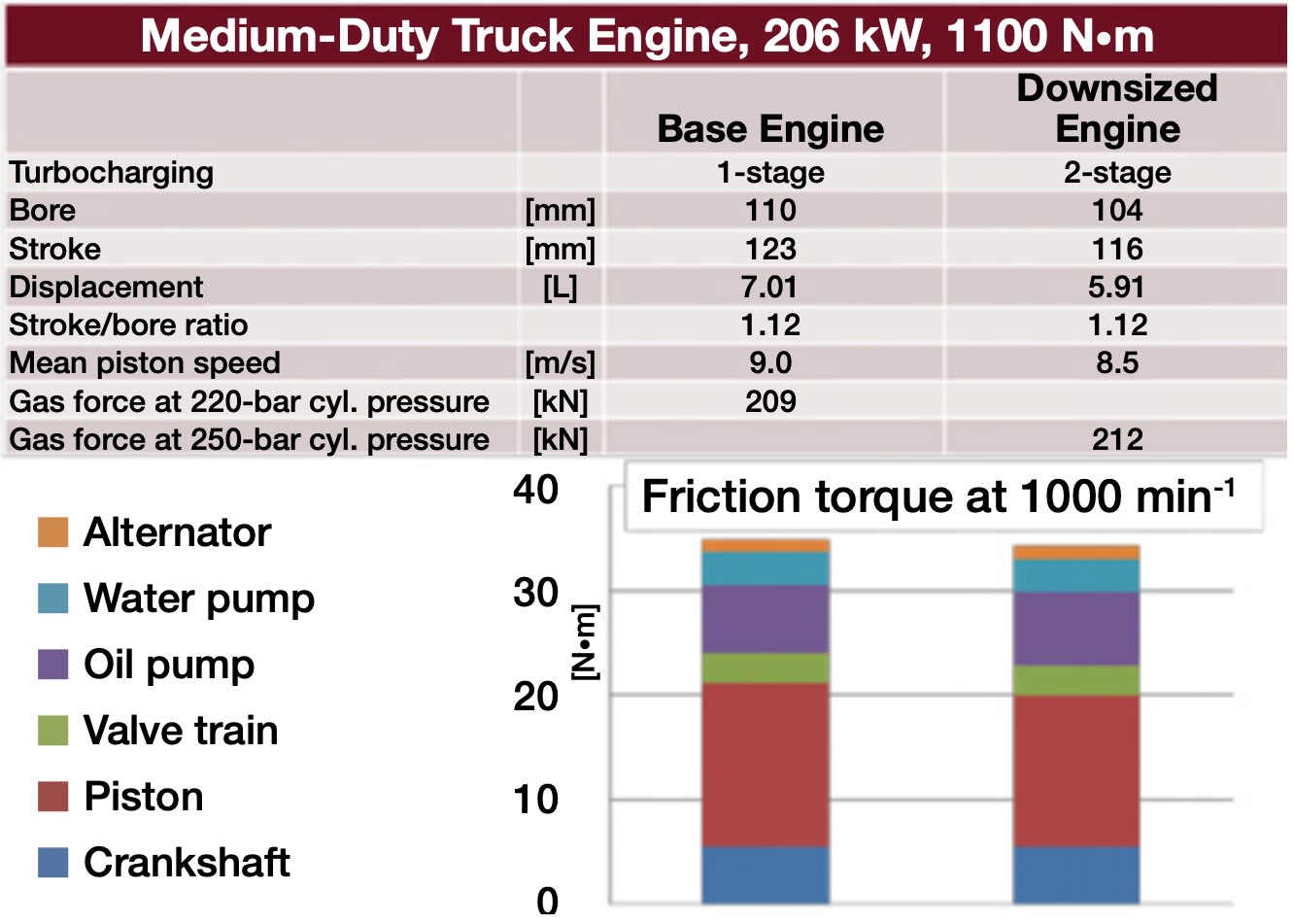
For the “downsized” variant of a medium-duty truck engine, the displacement is reduced proportionally to the bore and stroke keeping the stroke/bore ratio constant. This downsizing requires dual-stage turbo-charging leading to a peak pressure increase of approximately 30 bar (435 psi). In spite of a smaller bore diameter, the gas force remains approximately the same. Therefore, a reduction of the bearing diameters, the resultant bearing friction, and the oil flow through the bearings is not possible. The lower piston speed caused by the slightly smaller stroke at the same engine speed is the only friction-decreasing effect. This positive effect is partly consumed by the additional oil flow through the second turbocharger, which causes a higher oil pump driving power. The friction contributions of crank shaft, valvetrain, water pump, and alternator remain the same. Therefore, the friction estimate shows only a small difference in the frictional torque; merely the thermodynamic fuel consumption advantage via a shift in the operating point can be realized.

On the other hand, downsizing via a reduction in the number of cylinders would offer a significant potential for decreasing the engine friction. Due to dual-stage turbocharging and the measures necessary to cope with high peak pressure and power, the engine cost will increase significantly. This is compensated by the reduction in the number of cylinders due to a lower quantity of components. A cost comparison clearly shows that downsizing is financially attractive only if the displacement reduction is realized via a reduction in the number of cylinders.
Even the use of mass-balancing shafts for the elimination of the second order free inertia forces to optimize the NVH behavior of the four-cylinder is more than compensated by the cost advantage compared to a six-cylinder engine. Considering these friction and cost-reduction potentials, the introduction of large four-cylinder engines instead of the usual six-cylinder engines would be beneficial. A four-cylinder engine with a cylinder displacement of approximately 2L, which is common for HD engines, could successfully enter the performance class of 300 kW (400 hp), which represents the leading class in drive systems for 40-t long-haul trucks, and consequently provide a considerable cost-saving potential.

The significantly shorter length of the four-cylinder would free up space in the engine compartment, which could be used for the increased space required by the exhaust gas aftertreatment and cooling. In addition, a weight advantage of approximately 150 kg (330 lb) is to be expected even if mass-balancing shafts are used. The higher torque fluctuation due to the smaller number of cylinders would probably be the focus of development to meet customers’ NVH requirements. The main question that remains is customer acceptance of such engines in a rather conservative CV market.
Friction reduction
Application methods for thermal spray coatings to the cylinder running surface, which are available for series production application, offer potential for friction reduction. The FMEP (friction mean effective pressure) with the plasma-coated liner is about 12% lower than the baseline cast iron liner at rated speed. Up to 20% friction reduction has been reported at rated load in other studies. This technology, originating from passenger-car engines, has also been tested for CVs and large bore engines. It allows a free choice of the running surface material independent of the basic material of the cylinder liner.
It is common practice in light-/medium-duty engines to use crankcases with integrated cylinder liners (so-called parent bore). If this practice is adopted in HD engines instead of using wet cylinder liners, significant potential regarding production costs of the crankcase and cylinder spacing could be realized. In case of an engine overhaul, the worn cylinders would have to be bored out and a new spray coating applied, instead of exchanging the separate cylinder liners. Special overhaul pistons with slightly increased diameter would not be required for this; however, corresponding production facilities would be needed for carrying out such overhaul work.
Crankshaft main and connecting rod big end bearings are a significant source of friction in engines. The relative frictional torque for different subassemblies of the engine and crankshaft contributes about 14% of the total engine friction. At rated speeds and loads, this contribution can increase to 25%. There is potential to reduce the crankshaft friction by reducing the main and connecting rod journal diameters.

A reduction in the main bearing diameter decreases the quantity of oil flowing through the bearing. This reduces the oil demand from the oil pump, lowering the parasitic losses. This reduction in main bearing diameter goes opposite to the trend of increasing specific power and peak cylinder pressure if a counter-effect is not provided by manipulating the connecting rod bearing. A unique, patent-pending design has been proposed by FEV in which a reduction in the main bearing diameter is balanced by an increase in the connecting rod bearing diameter to the extent that the main journal and crank pin diameters are equalized. This approach enables the crankshaft stiffness to be maintained and the overall oil consumption to be reduced, thereby reducing the oil pump demand and parasitic losses.
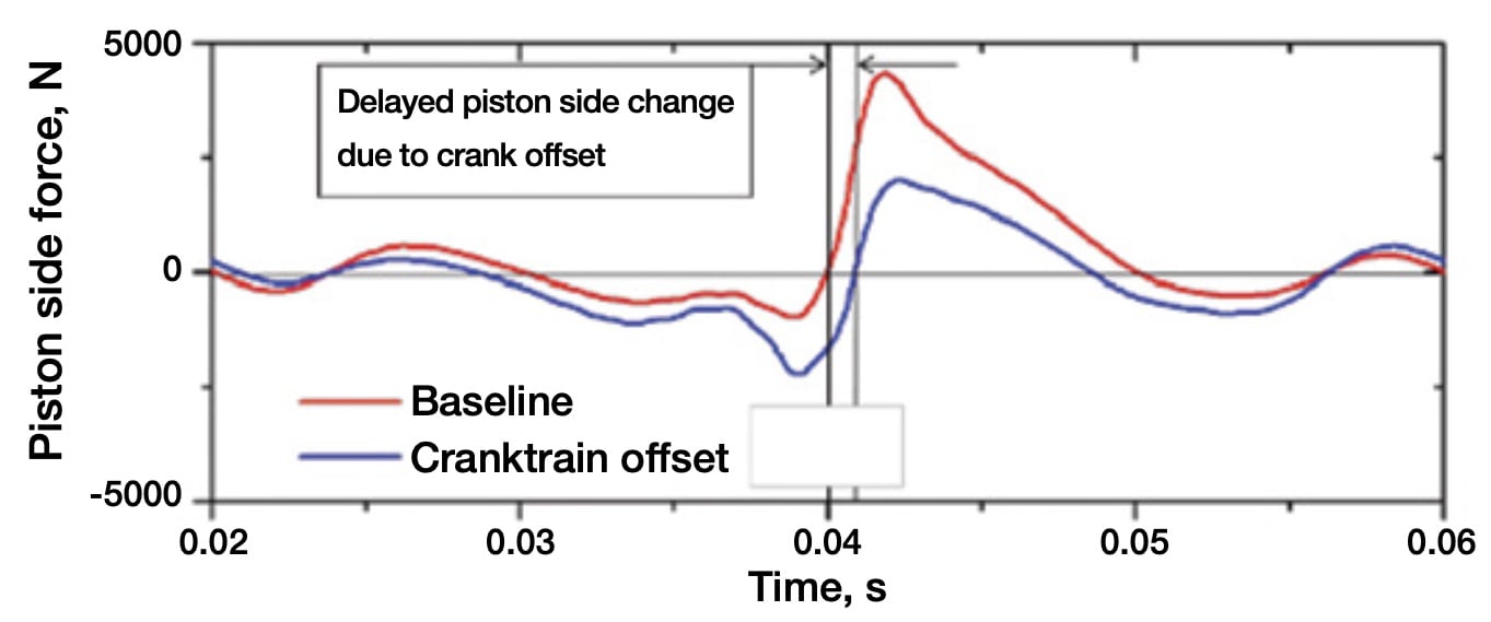
Another method of reducing friction forces in the cranktrain mechanism is to introduce an offset between the cylinder and crankshaft axes. Motion simulation can be used to predict the resultant frictional forces and to optimize the magnitude of offset. In a comparison of a time-based simulation of piston side force between an offset crankshaft and a “baseline” without offset, the friction force peak created by the combustion event is reduced to about 50% because of the crankshaft offset. There is a corresponding increase in the friction force during the compression stroke, but the magnitude is lower than the combustion event and the net effect is an overall reduction in the friction force and torque. The exact amount of offset to minimize the piston friction needs to be confirmed for every engine design based on simulation and will vary slightly with the cranktrain geometry.
Variable compression ratio (VCR)
High levels of boosting and specific power outputs are leading to high PCP, which is driving the need for the entire mechanical structure of the engine to be significantly strengthened. VCR technology presents an alternative solution by decreasing the CR at high loads, so that the PCP does not exceed the allowed level of an existing engine structure. Some possible applications for VCR systems in commercial engines could be:
- Performance upgrades on existing engines to increase specific power output
- Improvement of fuel consumption together with the introduction of high EGR rates in spite of a limited PCP in an existing engine
- For multi-fuel operation to increase the CR depending on ignition performance or cetane number of the fuel used.
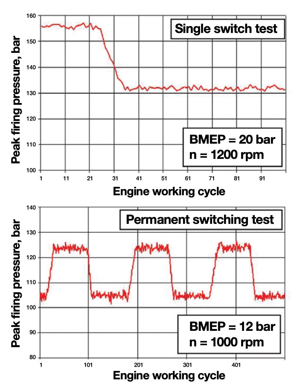
There are various VCR systems available that have the potential for a continuous variation of CR or may have only a step change. Continuous variation mechanisms have been shown to require major redesigns when applied to existing engines. FEV has developed a two-stage VCR system for a passenger-car gasoline engine as well as for a HD diesel engine application. In this 2-stage VCR system, the connecting rod length variation is realized by means of rotation of an eccentric bearing in the connecting rod small end. The moment acting on the eccentric, resulting from superimposed gas and inertia forces, is used to adjust the connecting rod length. This is the key feature to meet a cost-effective VCR solution, because no expensive and power-consuming actuators are needed and all functional elements are concentrated into only one component, the connecting rod.
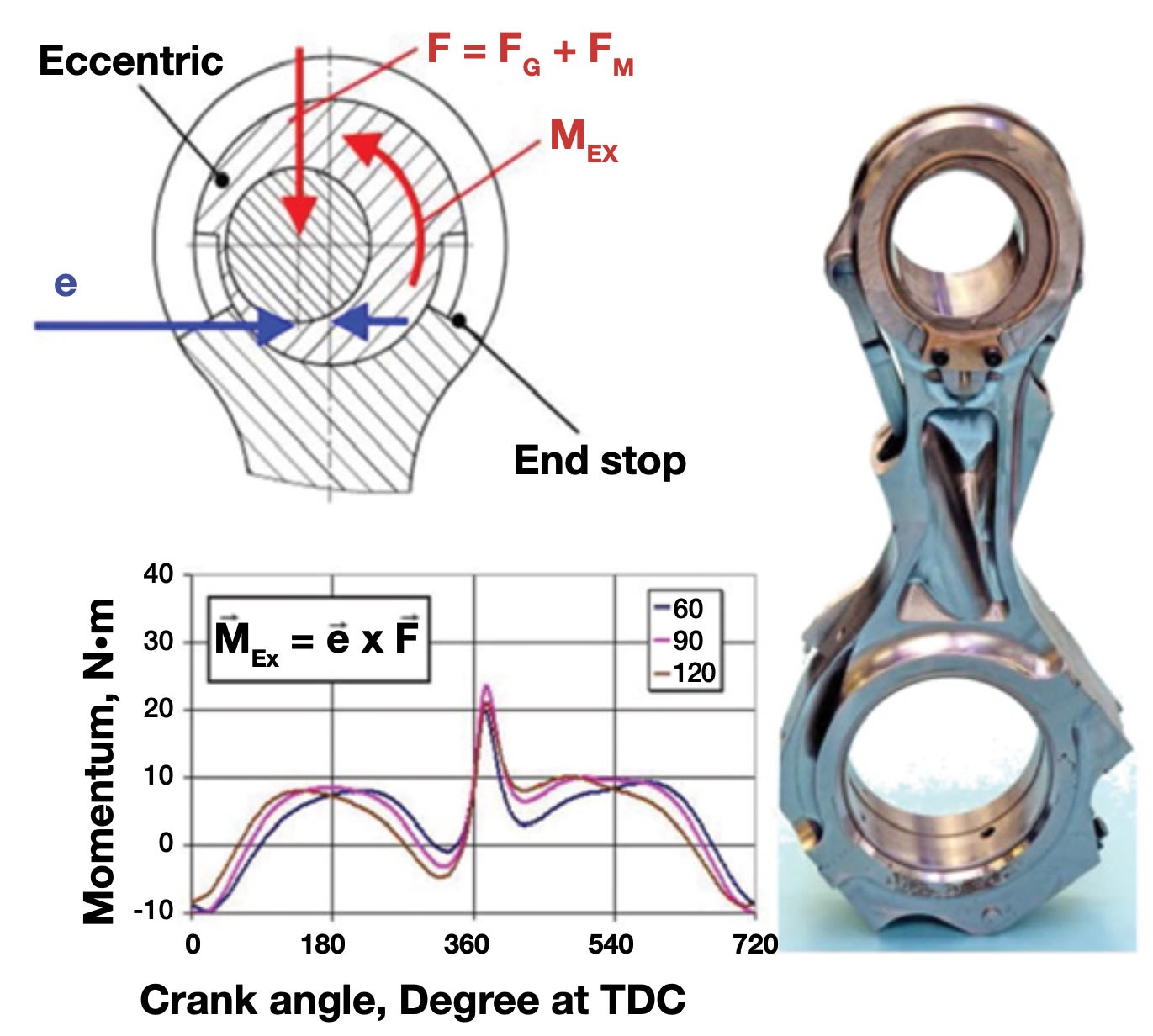
This design also will allow the VCR system to be incorporated into an existing engine with minimal design changes. The eccentric moment takes on positive as well as negative values during a combustion cycle, making possible an adjustment in both directions.
A switching test was conducted on a HD diesel engine with a 125-mm (4.92-in) bore. The peak firing pressure was 180 bar (2.6 ksi) and the CR was switched between 14 and 17. The results showed a very consistent CR switching behavior for the entire test procedure. No abnormal wear or cracks were detected on any of the components.
Cylinder head design
Constantly increasing PCP combined with a high power density poses great challenges in particular to the cylinder head. The selection of materials and the design principle or component geometry are the key issues for the layout. Increasing the material strength is a suitable means to improve the HCF (high-cycle fatigue) behavior. Consequently, some manufacturers have made the move from the traditional grey cast iron (GJL) to cast iron with vermicular graphite (GJV).
As an example, GJV450 material tolerates the high-frequency load from the combustion pressure in the cylinder very well and allows peak pressures far beyond 200 bar (2.9 ksi) without the need for detailed optimization of the geometry in the highly loaded areas as required for grey cast iron (GJL250). The heat conductivity, which compared to GJL is significantly reduced, causes an essential aggravation regarding thermo-mechanical fatigue (low-cycle fatigue, LCF) in the thermally highly loaded areas, in particular the valve bridges in the flame deck. Cracks in the valve bridges can be successfully avoided only by intensive cooling and drastic reduction of the wall thicknesses in these areas.
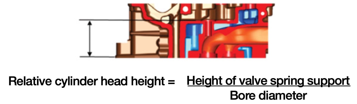
In the early design stage of a cylinder head, great attention must be paid to provide a sufficient width for the valve bridges when determining the valve positions and sizes to meet the requirements regarding cooling. This may well mean that compromises regarding the valve diameters and consequently the cross sections available for the gas exchange have to be made in order to achieve an adequately acceptable number of thermal load cycles corresponding to the targeted engine lifetime. The cylinder head height is an essential boundary condition for the achievable global stiffness of the cylinder head and with that an indicator for the admissible peak pressure.
A further design feature that positively influences the stiffness of the cylinder head is the cast injector dome. In comparison, a separate, inserted injector sleeve offers more favorable conditions for cooling in the thermally highly loaded area around the injector and between the valves. Furthermore, it is beneficial for casting the cylinder head, as the water jacket core is connected to the outside via the central nozzle area. An intermediate deck that can advantageously be used to guide the coolant to the crucial areas can be realized much more easily in the casting design.
An injector sleeve, however, cannot take on a supporting function in the cylinder head structure. This can, for example, be compensated for by a material of higher strength. These influences suggest that for engines with rather moderate power density and cylinder peak pressure capability, but high lifetime requirements, the material GJL or possibly in a variant with higher strength compared to the standard material GJL250, in connection with the cast injector dome is the most efficient alternative. This material is also very cost efficient.
For engines with higher power density and consequently higher thermal load on the cylinder head, the requirement of creating optimal boundary conditions for the cooling is gaining in importance. This is a strong indication for using an injector sleeve. Extreme peak pressure requirements might require the use of GJV to achieve HCF durability; at the same time the LCF problem increases with increasing power density.
The base-engine technologies discussed here present options to meet the emissions and fuel-economy targets in the near future. These technologies have demonstrated their potential in the laboratory environment or in light-duty production applications, and are readily available for implementation into commercial engines.
This article is based on SAE International technical paper 2014-01-2325 written by Michael Franke, Shirish Bhide, Jack Liang, Michael Neitz, and Thomas Hamm of FEV North America Inc. and FEV GmbH.
More From SAE Media Group
Off-Highway Engineering
Mahle, Liebherr Develop Active Pre-Chamber for Hydrogen ICE
Off-Highway Engineering
Cummins New X15 Engine Meets Upcoming Regs While Boosting Efficiency
Automotive Engineering
2022 Nissan Rogue Gets a VC Turbo Triple
Automotive Engineering
Audi's New V6 Diesel to Feature Electric Turbocharging, New NOx Technology
Automotive Engineering
Future ICEs: What Comes After 2025?

Automotive Engineering
Cooled EGR Shows Benefits for Gasoline Engines
Automotive Engineering
Reconsidering CNG as an Alt-Fuel Solution
Automotive Engineering
Injecting a Sense of Urgency to Clean up Diesels
Automotive Engineering
New Engines 2016
Automotive Engineering
Achates Powers toward Production
Automotive Engineering
Achates Aims at 2025 Light-truck Power
Off-Highway Engineering
Cummins Unveils New B7.2 Diesel Engine
Automotive Engineering
Mahle’s Pre-Chamber MJI Technology Is Sparking Ignition Advances
Automotive Engineering
Extending the ICE Age: Hyundai Optimizing Engines and Fuels
Off-Highway Engineering
Westport Awarded LNG Development Program
Off-Highway Engineering
Detroit DD15 Gen 5 Showcases Durability of New Diesel Tech
Off-Highway Engineering
Off-highway Calibration Challenges — Big and Complex
Automotive Engineering
'Reman' Engine Market Steady, but Complexity Challenges Production Efficiency
Automotive Engineering
JLR's All-New 2015 Modular Engines Feature Roller-Bearing Cams, Balance Shaft
Off-Highway Engineering
Navistar Updates A26 Engine, Improves FE by 4%
Automotive Engineering
Mercedes Shows Its Metal and Chooses Steel over Aluminum
Off-Highway Engineering
Iveco Pursues Natural Gas in Stralis NP Models
Off-Highway Engineering
Could This Infinitely Variable Compression Mechanism Be the Next Piston Engine Game-Changer?
Off-Highway Engineering
SwRI: CHEDE Consortium Closing in on 55% HD Diesel-Engine Efficiency
Automotive Engineering
2015 Engines Ride a Technology Tidal Wave
Automotive Engineering
Spark of Genius
Automotive Engineering
Balancing GDI Fuel Economy and Emissions
Automotive Engineering
Delphi and Hyundai GDCI Program Aims to Top Diesel Efficiency
Automotive Engineering
Slick Solutions for Friction Reduction
Top Stories
INSIDERManufacturing & Prototyping
![]() How Airbus is Using w-DED to 3D Print Larger Titanium Airplane Parts
How Airbus is Using w-DED to 3D Print Larger Titanium Airplane Parts
INSIDERManned Systems
![]() FAA to Replace Aging Network of Ground-Based Radars
FAA to Replace Aging Network of Ground-Based Radars
NewsTransportation
![]() CES 2026: Bosch is Ready to Bring AI to Your (Likely ICE-powered) Vehicle
CES 2026: Bosch is Ready to Bring AI to Your (Likely ICE-powered) Vehicle
NewsSoftware
![]() Accelerating Down the Road to Autonomy
Accelerating Down the Road to Autonomy
EditorialDesign
![]() DarkSky One Wants to Make the World a Darker Place
DarkSky One Wants to Make the World a Darker Place
INSIDERMaterials
![]() Can This Self-Healing Composite Make Airplane and Spacecraft Components Last...
Can This Self-Healing Composite Make Airplane and Spacecraft Components Last...
Webcasts
Defense
![]() How Sift's Unified Observability Platform Accelerates Drone Innovation
How Sift's Unified Observability Platform Accelerates Drone Innovation
Automotive
![]() E/E Architecture Redefined: Building Smarter, Safer, and Scalable...
E/E Architecture Redefined: Building Smarter, Safer, and Scalable...
Power
![]() Hydrogen Engines Are Heating Up for Heavy Duty
Hydrogen Engines Are Heating Up for Heavy Duty
Electronics & Computers
![]() Advantages of Smart Power Distribution Unit Design for Automotive...
Advantages of Smart Power Distribution Unit Design for Automotive...
Unmanned Systems
![]() Quiet, Please: NVH Improvement Opportunities in the Early Design...
Quiet, Please: NVH Improvement Opportunities in the Early Design...