


DEF Delivery Modeling for SCR Systems
Researchers characterize a 0-D model of a urea delivery module, oriented to model-based control and to the simulation of the system response to fault injections, finalized to diagnosis validation.

The progressive tightening of the limits defined by antipollution regulations in many countries has led the industry to develop control and pollutants abatement technologies of increasing sophistication and effectiveness.
To achieve more stringent emissions limits in a diesel engine, it is no longer sufficient to implement control actions within the combustion chamber, such as multiple injections, exhaust gas recirculation (EGR), fluid dynamics optimization, turbocharging, etc., but it has become necessary to adopt exhaust emissions aftertreatment systems.
A significant reduction of NOx concentration in the exhaust gas can be achieved through selective catalytic reduction (SCR), which essentially operates by reducing the NOx to nitrogen (N2) and water vapor (H2O). The basic operating principle of an SCR system consists of the addition of ammonia as a reducing reagent, inside an appropriate catalytic reactor.
The problem of direct use of ammonia, a substance considered toxic, as a reagent has been overcome through the storage and transport of the reductant in a more secure form, represented by a water-based solution (32.5%) of urea (CO(NH2)2), called diesel exhaust fluid (DEF). This compound has the characteristic of not being classified as hazardous to humans and the environment, and not being flammable; therefore it can be used with fewer precautions than pure ammonia.
It is typically stored onboard the vehicle inside dedicated tanks, and injected into the gas flow upstream of the converter. DEF then transforms into ammonia, due in part to the high temperatures of the exhaust gas. Activation reactions are facilitated by the presence of the catalytic converter that lowers the activation energy, allowing the systems to achieve high reduction efficiencies in a rather wide temperature range, 170-500°C (338-932°F). SCR-system performance strongly depends on the correct injection of reagent amount, which, to be highly efficient in the reduction of NOx, must mix homogeneously with the exhaust gas flow.
A pump connected to the DEF tank provides the desired injection pressure. It is directly controlled by the engine control unit (ECU) or, as an alternative, by a dedicated control unit integrated in the dosing system, called a dosing control unit (DCU). The communication between the two control units in this case is implemented via a CAN line.
The pressurization system requires, in addition to a dedicated control system that monitors and coordinates the operation at the various injection pressures, a diagnostic system that can identify pre-determined faults. The recovery actions are designed to ensure full compliance with the standards imposed by the law and, at the same time, to guarantee preservation of the system itself and of its components.
For these reasons, a model of the DEF supply system is very useful during the development of a new system. It can be used for testing the control strategies to be implemented in the real-time controller.
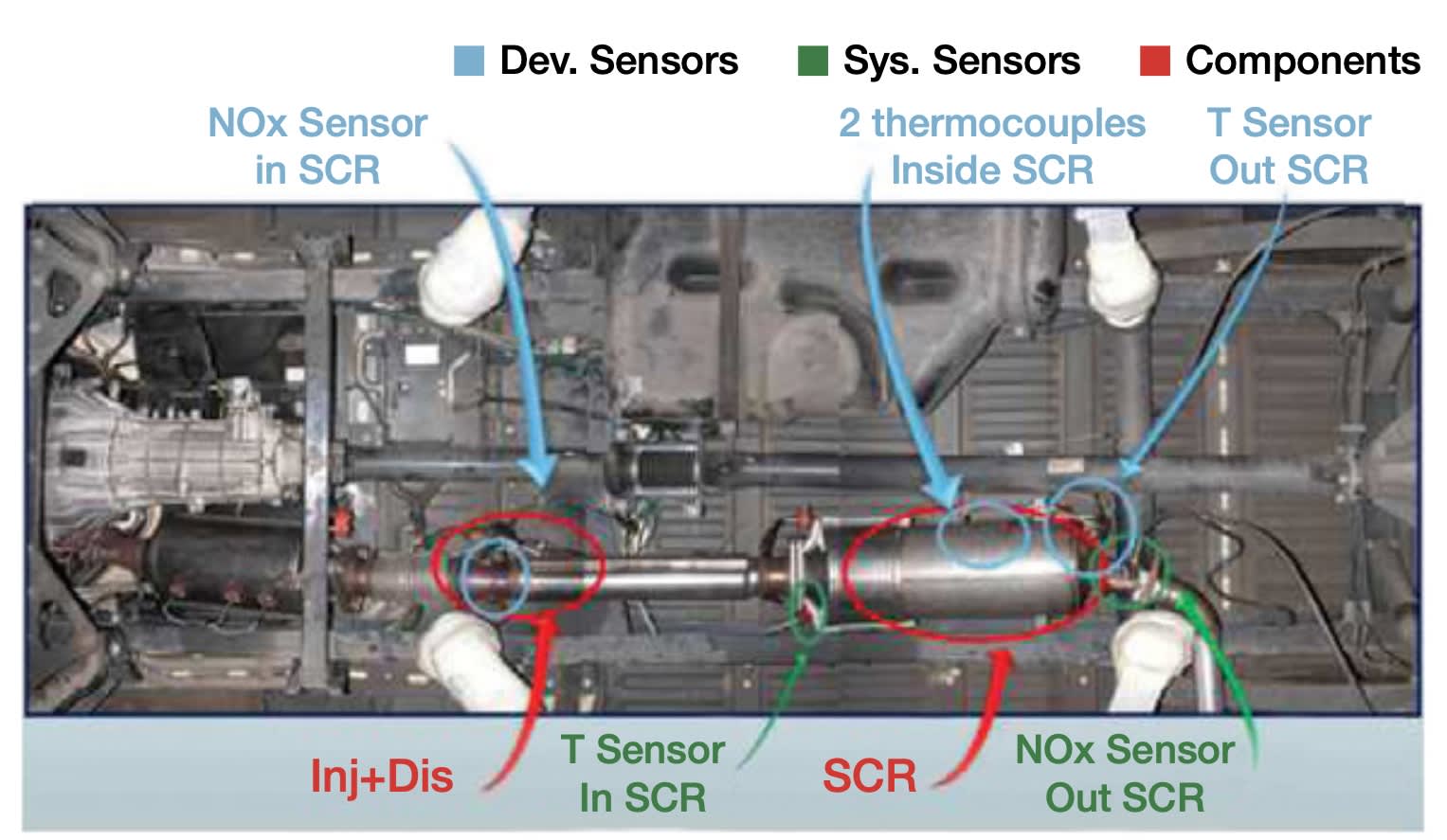
SCR: System overview
DEF is a colorless liquid, odorless and non-hazardous to humans. There are no specific problems related to its transport in vehicles, and it does not require any special storage conditions. However, one characteristic to be carefully considered is its freezing point, located at temperatures easily achievable worldwide, especially in the winter season. To prevent solidification, many commercial systems perform an active heating of the ducts that contain the DEF, thus allowing operation at temperatures far below the freezing point.
In addition to this, they are typically provided with a system for thawing the tank and pump content to liquefy and thus make available to the injection system a certain quantity of DEF, in conditions of external critical temperature, within a certain given time limit, as specified by regulations. Another critical aspect is the tendency of the DEF solution to create solid deposits, which could clog the injector, if not properly filtered or removed.

DEF delivery systems are designed and controlled to reduce NOx emissions. When the concentration of NH3 in the catalytic converter is estimated insufficient for the reduction of NOx, the proper amount of DEF is injected into the exhaust gas through an injector, placed immediately upstream of the catalytic converter, and oriented so as to ensure a proper distribution of urea and water particles into the main flow. The pressure in the injection system is generated by a volumetric pump driven by a dc motor, and it is usually controlled at a constant value. A plausible DEF injection pressure range is currently between 6-10 bar (87-145 psi).
For purposes here, researchers from Magneti Marelli and University of Bologna focused on the development of a control-oriented model of the urea solution pressurization system, strongly based on a physical description of the main electrical and fluid dynamics phenomena that characterize the UDM (urea delivery module). The purpose of the model is to support the development, testing, and validation phases of the UDM control and diagnostic system.
Model validation and diagnostic tests

The implementation of a zero-dimensional UDM model in Simulink environment was achieved via the merging of the two mathematical models, hydraulic and electro-mechanical.
Calibration data consisted of parameters extracted from the datasheets of various components, and of characteristic maps that were identified via specifically designed experiments. Once this phase was completed, the model was validated by comparing the results with different sets of experimental data.
The injector was always kept closed during such tests, therefore considering a system operating cycle composed of three steps: pressurization, steady-state at injection pressure, and depressurization.
A fairly structured diagnostic system is required to monitor the state of health of the UDM’s various components, and to satisfy the condition of “zero leakage” imposed by legislation. During system pressurization various abnormal situations may occur, due to possible faults, e.g., the appearance of a leak on the pressurizing line, the drift of a sensor, etc.
The aim of the diagnostic system is to promptly identify a system fault, while avoiding false alarms, and to store a diagnostic code while activating the corresponding recovery strategy.
Diagnosis can be essentially of two types, electrical or functional. Electrical diagnoses are carried out by comparing the electrical input parameters with pre-defined limits. A typical case is a sensor failure, which usually results in an output beyond the threshold values. The functional diagnoses are instead performed by analyzing the parameters that contribute and interact with each other, to ensure correct operation (functionality) of the system.
To provide some examples of the diagnostic functionalities that have been implemented thanks to the fully model-based approach, four functional diagnoses were examined.
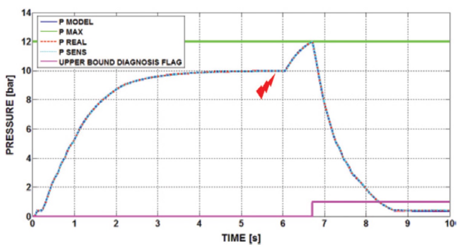
Upper bound. To test the upper bound condition, an erroneous configuration of the control system was simulated forcing maximum duty-cycle operation of the pump, or motor driven at battery voltage (12 V). A 12-bar (174-psi) threshold was set as maximum allowable pressure, and a graph was generated showing the diagnostic systems reaction when the fault was injected.
The diagnostic system detects this anomaly and turns off the electric motor, assuming that the vehicle electrical wiring is equipped with a second emergency switch.
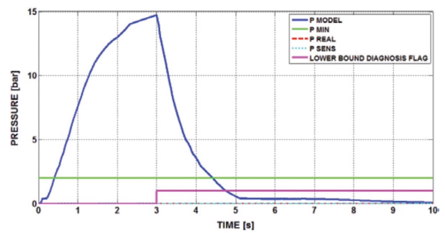
Lower bound. The lower bound diagnosis is activated when the system cannot reach a minimum pressure level within a certain time interval, considering as initial instant the power supply activation (OFF/ON transition). The fault may be due to the decoupling between the electric motor and the pump, or to a very substantial loss of DEF caused by partial or total failure of the supply pipe. To test this diagnostic feature, an infinitely wide hydraulic leak was inserted in the model, as if it were present in the plant before system startup.
A variation of the virtual model pressure clearly resulted from the increase of the applied voltage. The pressure level detected by the sensor, however, remained at zero value, which is below the minimum threshold value (2 bar/29 psi). This condition, together with the time limit expiration (3 s), triggers the relative flag, interrupting the motor control voltage supply.
Tracking. The tracking diagnosis has been virtually validated by setting a maximum deviation limit between the pressure level measured by the sensor, and the corresponding estimated value.
This type of monitoring effort is necessary to detect a malfunction due to small DEF leaks in the pressurized system, or performance deterioration of any of the components.
The most delicate aspect of this analysis is the definition of the maximum deviation to be tolerated during operation. Indeed, if this threshold is too narrow, false positives may occur, typically due to production-induced components variability. If the dynamic threshold is too large, it potentially makes the diagnosis ineffective.
The virtual test was carried out with the hypothesis that the performance of a given new component may present a spread of up to 2% due to production variability. The test consisted of a pressurizing phase up to 10 bar (145 psi), and subsequently a leak was induced in the modeled hydraulic circuit, to validate the response of the diagnostic system, and to assess its performance.
A test was undertaken for two different leak dimensions. The first case considered a leakage flow of 0.8 L/h, at 10-bar (145-psi) system pressure. In this situation, the diagnostic system detected the fault and it consequently stopped the motor.
In the second test a smaller leak was simulated, which represented the lower limit in terms of diagnostic capabilities. The diagnostic system was unable to detect the loss, equal to about 0.7 L/h.
Pressure sensor plausibility. In this example only the pressure sensor saturation test was considered. Saturation can occur above or below the target pressure.
The sensor saturation below target pressure fault, not being diagnosable by electrical diagnostics, would lead to controller saturation in the effort to reach the target pressure, causing an unconditional increase of the actual pressure inside the pipe, even above the upper bound limit.
In this simulation, the sensor output was virtually saturated to 9 bar (130 psi), at time equal to 5.6 s. Using the VS (virtual sensor) as a reference, the appropriate recovery action can be triggered, and stop the motor.
The pressure transducer saturation above target pressure is potentially less harmful than the previous example. In this case the controller continues to take into account a negative error, and therefore it decreases the supply voltage, until the motor eventually stops. The sensor saturation was forced at about 5.7 s, at a value of 10.5 bar (152 psi). The comparison done once again with the VS output allowed isolating the fault, and immediately triggered the motor shut down.
Results and future work
The realization of the 0-D model of the UDM system, together with the development of both the control and the diagnostic systems models, gave strong indications of what might be the most critical issues related to in-field use.
The zero-dimensional model showed a good and encouraging agreement with the experimental data, and one issue under investigation is the difficulty that emerged in diagnosing small leaks on the DEF injection pipe. To overcome this problem, a limited pump dispersion is needed, but this would have a negative impact on system costs.
Another certainly interesting aspect is the accuracy of the pressure VS, and its impact on improving the diagnostic capability during transient operation.
Future work will include the evaluation of the system behavior during injection events. The influence of pressure waves will be assessed, with the aim to achieve a dedicated diagnosis system. Also assessed will be the implementation of adaptive models to recover the system dispersion and aging.
This article is based on SAE International technical paper 2015-26-0090 by Federico Stola, Matteo De Cesare, and Luca Lacchini, Magneti Marelli SpA Powertrain Division; Nicolò Cavina, University of Bologna; and Sandeep Sohal, Magneti Marelli India Powertrain Pvt Ltd.
More From SAE Media Group

Tech Briefs
Making Diesel Engines Nearly Emission-Free
Off-Highway Engineering
The Complicated Future of Off-Highway Engines
Off-Highway Engineering
Off-highway Calibration Challenges — Big and Complex
Off-Highway Engineering
Innovation Is at the Core of Engine Design
Off-Highway Engineering
Advances for Off-highway Engine Design
Off-Highway Engineering
Proven Solutions to Enhance Customer Value
Off-Highway Engineering
Heavy-Duty Engine Design
Off-Highway Engineering
Case CE Upgrades 621F and 721F Wheel Loaders to Meet Tier 4 Final
Off-Highway Engineering
Many ICE Paths Lead to Reduced Emissions
Off-Highway Engineering
Combustion Modeling in Heavy-duty Diesels
Off-Highway Engineering
Waste Heat Recovery for the Long Haul
Off-Highway Engineering
Engine Developers Increase Efforts to Decrease Fuel Usage
Off-Highway Engineering
Cummins Unveils New B7.2 Diesel Engine

Automotive Engineering
The Inside Story on Thermal Management
Off-Highway Engineering
Global Emissions Regs Demand Differing Engine Strategies
Automotive Engineering
Cooled EGR Shows Benefits for Gasoline Engines
Automotive Engineering
Achates Aims at 2025 Light-truck Power
Off-Highway Engineering
Reshaping the Mobile-hydraulic Ecosystem
Battery & Electrification Technology
Ultracapacitor Solutions to Address Energy-Storage Needs of Vehicles
Off-Highway Engineering
Calibration and Complexity
Off-Highway Engineering
FPT Plans Engines for Complex Market
Off-Highway Engineering
Combustion Engines Carry on in Construction
Off-Highway Engineering
Doosan Introduces Tier 4 Final Wheeled Excavator
Off-Highway Engineering
Life-cycle Planning — Design and Calibration for Ultimate Efficiency
Off-Highway Engineering
Maintaining Protection for Next-Gen HD Engine Lubricants
Off-Highway Engineering
Off-Highway Emissions Set to Get Stricter
Off-Highway Engineering
Iveco Pursues Natural Gas in Stralis NP Models
Off-Highway Engineering
Development Trends for Heavy Engines
Top Stories
INSIDERManufacturing & Prototyping
![]() How Airbus is Using w-DED to 3D Print Larger Titanium Airplane Parts
How Airbus is Using w-DED to 3D Print Larger Titanium Airplane Parts
INSIDERManned Systems
![]() FAA to Replace Aging Network of Ground-Based Radars
FAA to Replace Aging Network of Ground-Based Radars
NewsTransportation
![]() CES 2026: Bosch is Ready to Bring AI to Your (Likely ICE-powered) Vehicle
CES 2026: Bosch is Ready to Bring AI to Your (Likely ICE-powered) Vehicle
NewsSoftware
![]() Accelerating Down the Road to Autonomy
Accelerating Down the Road to Autonomy
EditorialDesign
![]() DarkSky One Wants to Make the World a Darker Place
DarkSky One Wants to Make the World a Darker Place
INSIDERMaterials
![]() Can This Self-Healing Composite Make Airplane and Spacecraft Components Last...
Can This Self-Healing Composite Make Airplane and Spacecraft Components Last...
Webcasts
Defense
![]() How Sift's Unified Observability Platform Accelerates Drone Innovation
How Sift's Unified Observability Platform Accelerates Drone Innovation
Automotive
![]() E/E Architecture Redefined: Building Smarter, Safer, and Scalable...
E/E Architecture Redefined: Building Smarter, Safer, and Scalable...
Power
![]() Hydrogen Engines Are Heating Up for Heavy Duty
Hydrogen Engines Are Heating Up for Heavy Duty
Electronics & Computers
![]() Advantages of Smart Power Distribution Unit Design for Automotive...
Advantages of Smart Power Distribution Unit Design for Automotive...
Unmanned Systems
![]() Quiet, Please: NVH Improvement Opportunities in the Early Design...
Quiet, Please: NVH Improvement Opportunities in the Early Design...