


Improvements in Measurement of Permeability and Permittivity
Errors associated with reflections can be suppressed.
The two-transmission method is an improved method of determining, from microwave measurements, the complex permeability and complex permittivity of a sample of a material typified by a lossy dielectric or a magnetic radar absorbing material. The two-transmission method is so named because it involves two microwave transmission- measurement runs: one on the sample alone and one on a two-layer stack comprising the sample plus a layer of an acrylic material that has known permittivity and permeability. The name of the two-transmission method also serves to distinguish it from a prior method that involves microwave-reflection measurements with which errors have been associated.

In the frequency-domain variants in the waveguide laboratory setup, it is necessary to perform a through-reflect-line calibration of the waveguide apparatus that includes a holder in which the sample or the sample/acrylic stack is to be placed. The sample or the sample/ acrylic stack must be accurately machined to fill the holder to ensure that only the dominant waveguide mode is present. The S-parameters of the sample or the sample/acrylic stack are obtained from the network-analyzer measurements. Then the complex permittivity and permeability are extracted from the S-parameters by means of a suitable algorithm, which is typically based on equations known as the NRW formulas [wherein "NRW" signifies the surnames (Nicolson, Ross, and Weir) of the originators of the equations] that are well known to specialists in this art. The NRW formulas require transmission and reflection measurements. If, as in the two-transmission method, the NRW formulas cannot be used, then an iterative method such as a Newton two-dimensional root search is used.
A reflection measurement can entail a path-length difference that can give rise to a large error. A position-correction factor can be used in conjunction with both forward and reverse measurements to account for this error. However, the use of transmission measurements (as in the two-transmission method) that are independent of the position of the sample eliminates this source of error and the need for a correction factor, thus leading to more accurate results.
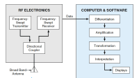
The process for characterizing a sample in a focus arch differs somewhat from that in a waveguide setup. In the frequency-domain variants, a focus arch (see figure) includes two wideband antennas, a network analyzer for making the S-parameter measurements, a sample holder, and two dielectric lenses that collimate the beams from the antennas in the region that contains the sample holder. As in the waveguide setup, a calibration must be performed, and the complex permittivity and permeability are extracted from the S-parameters. Error is introduced if the sample is not properly positioned and oriented at the reference plane.
Unlike in the waveguide setup, the process of extracting the complex permittivity and permeability from the S-parameters includes a frequency windowing subprocess to knock down side-lobes that occur in another subprocess in which data are transformed to the time domain. This frequency windowing causes a loss of accuracy at the edges of the frequency band represented by the window. In the time domain, the data are time-gated to remove unwanted sample/antenna interactions. Finally, the data are transformed back into the frequency domain, and the applicable algorithm for extracting the complex permittivity and permeability are applied.
For the focus arch, the process can be simplified if the measurements are made in the time domain. For this purpose, the network analyzer is replaced with a digital oscilloscope that includes a time-domain reflection/time-domain transmission (TDR/TDT) module. Making measurements in the time domain eliminates the need for frequency windowing and transforming to the time domain, thereby making it possible to retain the accuracy of data at the window frequency-band edges. The direct time-domain measurements are gated as described above and then transformed to the frequency domain for extraction of the complex permeability and permittivity as described above.
This work was done by Kirt J. Cassell of the Air Force Institute of Technology for the Air Force Research Laboratory.
AFRL-0093
This Brief includes a Technical Support Package (TSP).
Improvements in Measurement of Permeability and Permittivity
(reference AFRL-0093) is currently available for download from the TSP library.
Don't have an account?
More From SAE Media Group


Aerospace & Defense Tech Briefs
Traveling-Wave Wide-Band Microstrip Antennas
Aerospace & Defense Tech Briefs
From DC to Daylight — How Innovations in Microwave Absorbers Shield the Warfighter
RF & Microwave Technology
Measuring Radar Cross Section with Handheld VNAs

Electronics & Sensors INSIDER
Researchers Demonstrate a High-Speed Electrical Readout Method for Graphene Nanodevices
Aerospace & Defense Tech Briefs
Pulse Analysis Techniques for Radar and Electronic Warfare
Aerospace & Defense Tech Briefs
An Integrated Framework for Complex Radar System Design
Aerospace & Defense Tech Briefs
Measuring Impact Damage to Toughened CFRP Laminates with Time Domain Reflectometry
Tech Briefs
Deployable Fresnel Rings
Tech Briefs
Products of Tomorrow
Aerospace & Defense Tech Briefs
Miniaturized GPS Controlled-Reception-Pattern Antenna Array
Software Tech Briefs
Analysis of Spiral Resonator Filters

Software Tech Briefs
Picking the Pattern for a Stealth Antenna
RF & Microwave Technology
Antenna Electronically Steered Using MEMS Phase Shifters
RF & Microwave Technology
Arcing and Vibration Tests of High-Power Patch Antennas
Electronics & Sensors INSIDER
New Tech May Lead to Smaller, More Powerful Wireless Devices

Photonics Tech Briefs
Stabilization of Phase of a Sinusoidal Signal Transmitted Over Optical Fiber

Electronics & Sensors INSIDER
Blocking Electromagnetic Radiation with the Flip of a Switch
Photonics & Imaging Technology
Terahertz Energy Focused by Credit Card-Sized Device to Generate High-Resolution Images
Tech Briefs
Inkjet Printing of Metamaterials

Overview
The document is a Master's thesis titled "Investigation of Frequency-Domain and Time-Domain Free-Space Material Measurements" authored by Captain Kirt J. Cassell at the Air Force Institute of Technology. The thesis focuses on the characterization of materials using electromagnetic measurements, specifically through frequency-domain and time-domain techniques.
The primary objective of the research is to develop and refine methods for accurately measuring the complex permittivity and permeability of materials. These properties are crucial for understanding how materials interact with electromagnetic fields, which has significant implications in various fields, including telecommunications, radar, and materials science.
The methodology section outlines a transmission-only approach to extract constitutive parameters from test samples. This involves using a rectangular waveguide and a free-space measurement system, which allows for precise characterization of materials without the complications that can arise from reflection measurements. The thesis emphasizes the importance of accurate material characterization in the design and optimization of electromagnetic systems.
The document is structured into several key sections, beginning with an introduction that presents the problem statement, scope, and organization of the thesis. The background section provides a review of existing literature and methodologies related to A-parameter systems and the NRW (Nicolson-Ross-Weir) algorithm, which is a critical tool for extracting material properties from measured data.
The findings of the research contribute to the existing body of knowledge by presenting new insights into the measurement techniques and their applications. The thesis also discusses the implications of these findings for future research and practical applications in the field of electromagnetic material characterization.
Overall, this thesis represents a significant contribution to the field, offering a comprehensive examination of advanced measurement techniques and their relevance to both theoretical and practical aspects of material science and engineering. The work is intended to aid in the development of more effective electromagnetic systems by providing a deeper understanding of material properties and their measurement.
Top Stories
INSIDERDefense
![]() New 3D-Printable Nanocomposite Prevents Overheating in Military Electronics
New 3D-Printable Nanocomposite Prevents Overheating in Military Electronics
Technology ReportSoftware
![]() Talking SDVs and Zonal Architecture with TE Connectivity
Talking SDVs and Zonal Architecture with TE Connectivity
NewsDesign
![]() 2026 Nissan Sentra Review: Putting the Pieces Together
2026 Nissan Sentra Review: Putting the Pieces Together
INSIDERDesign
![]() New Defense Department Program Seeks 300,000 Drones From Industry by 2027
New Defense Department Program Seeks 300,000 Drones From Industry by 2027
INSIDERDefense
![]() Anduril Completes First Semi-Autonomous Flight of CCA Prototype
Anduril Completes First Semi-Autonomous Flight of CCA Prototype
INSIDERDefense
Webcasts
Automotive
![]() SAE Automotive Podcast: Solid-State Batteries
SAE Automotive Podcast: Solid-State Batteries
Manufacturing & Prototyping
![]() SAE Automotive Engineering Podcast: Additive Manufacturing
SAE Automotive Engineering Podcast: Additive Manufacturing
Defense
![]() A New Approach to Manufacturing Machine Connectivity for the Air Force
A New Approach to Manufacturing Machine Connectivity for the Air Force
Software
![]() Optimizing Production Processes with the Virtual Twin
Optimizing Production Processes with the Virtual Twin
Automotive
![]() EV and Battery Thermal Management Strategies
EV and Battery Thermal Management Strategies
Aerospace
![]() How Packet Digital Is Scaling Domestic Drone Battery Manufacturing
How Packet Digital Is Scaling Domestic Drone Battery Manufacturing