


Antenna Electronically Steered Using MEMS Phase Shifters
This work contributes to development of relatively inexpensive electronically steerable antennas.
An experimental phased-array microwave antenna assembly includes an array of eight patch antenna elements connected to Microelectromechanical System (MEMS) phase shifters, by means of which the directional radiation pattern of the antenna can be controlled electronically. The antenna and the MEMS-based phase shifters were designed for a nominal operating frequency of 17 GHz. In addition, some 35-GHz MEMS phase shifters were designed, built, and tested. This work is part of a continuing effort to develop relatively inexpensive electronically steerable antennas.

The phase shifters are based on the concept of delay lines having various lengths selectable by use of electrostatically actuated MEMS switches. A reflection-delay-line phase-shifter architecture was chosen to make best use of the performance of the MEMS switches and to help minimize the overall dimensions of each phase shifter.
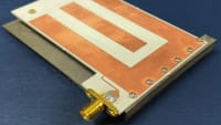
The phase shifters were fabricated on high-resistivity silicon substrates. Both two- and three-bit phase shifters were designed and built. Figure 1 shows one of the 17- GHz two-bit phase shifters as it looks before it is packaged. Each phase shifter includes a coplanar-waveguide (CPW) Lange directional coupler and two delay lines with shunt switches at the locations appropriate for switching the desired increments of phase. The switches are actuated in left-right pairs to obtain in ascending sequence phase increments of 0°, 90°, 180°, and 270°, respectively. Assuming that the delays along the two delay lines are equal, the microwave signals reflected from the closed switches add in phase with each other at the output terminal of the directional coupler with a phase shift equal to twice the delay associated with length of one delay line. The transmission line shown as a vertical line at the top, which is terminated in a CPW short circuit, is used in the 270° switch state.
In tests, the MEMS switches alone exhibited insertion loss <0.3 dB and isolation greater than 20 dB from DC to 40 GHz. The MEMS phase shifters were enclosed in packages that include external connectors for DC switching control signals and for the radio-frequency (RF) signals to be phase-shifted. The 17-dB MEMS phase shifters were tested and found to function with average insertion loss ≈2.5 dB and return loss >20 dB. The average insertion loss of the 35-dB phase shifters was found to be ≈3.3 dB.
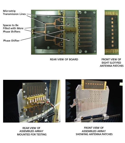
Eight packaged two-bit, 17-GHz MEMS phase shifters, tested and selected to be functional and nearly identical in operational characteristics, were mounted on a dielectric board that holds the array of antenna patches and the associated feed array of microstrip transmission lines (see Figure 2). The phase shifters were connected to a switch panel to provide DC switching signals to the MEMS switches. In a test in which the array was operated in a receiving mode, the array functioned well, exhibiting steering of the radiation beam to five available positions: 0°, +25°, -25°, +55°, and -55°.
This work was done by Ronald G. Polcawich, Daniel Judy, Jeffrey S. Pulskamp, and Steve Weiss of the Army Research Laboratory.
ARL-0033
This Brief includes a Technical Support Package (TSP).
Antenna Electronically Steered Using MEMS Phase Shifters
(reference ARL-0033) is currently available for download from the TSP library.
Don't have an account?
More From SAE Media Group
RF & Microwave Technology
Arcing and Vibration Tests of High-Power Patch Antennas
Tech Briefs
New Phase Shifter to Reduce Antenna Signal Loss
Tech Briefs
Cup Cylindrical Waveguide Antenna

Tech Briefs
Deployable Fresnel Rings

Tech Briefs
Toroidal Radiation Pattern Patch Antenna
RF & Microwave Technology
High-Cycle Life Testing of RF MEMS Switches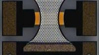
Aerospace & Defense Tech Briefs
Making Fully Digital Beamforming for Radar and Electronic Warfare Applications a Reality

RF & Microwave Technology
Microwave Energy Transmission for Aircraft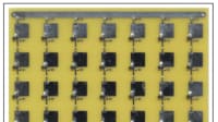

Tech Briefs
New Wireless System for Greater 5G Access
Tech Briefs
Aperture-Coupled Thin-Membrane L-Band Antenna

Aerospace & Defense Tech Briefs
Army and Universities Deploy New Warfighter Communication Technology
Tech Briefs
Quantum Sensor Enables Wide Spectral Coverage
Tech Briefs
Wireless, Wearable Transmitter
RF & Microwave Technology
High-Reliability MEMS Switches for Radio Frequency Applications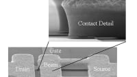
Tech Briefs
MCM Polarimetric Radiometers for Planar Arrays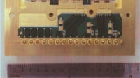
Automotive Engineering
Homing in on STEM Innovation

Aerospace & Defense Tech Briefs
Benefits and Challenges of Direct-RF Sampling for Avionic Platforms
RF & Microwave Technology
System Could Detect Concealed Person-Borne Bombs at a Distance
Tech Briefs
CMOS-Based Transceiver for 300 GHz
Overview
The document titled "Ku-Band Radio Frequency Microelectromechanical System Enabled Electronically Scanned Antenna" is a technical report authored by Ronald G. Polcawich, Daniel Judy, Jeffrey S. Pulskamp, and Steve Weiss, published by the U.S. Army Research Laboratory in October 2007. It presents research conducted between May 2005 and April 2006, focusing on advancements in antenna technology utilizing microelectromechanical systems (MEMS).
The report outlines the development of a Ku-band electronically scanned antenna, which is designed to enhance communication and radar capabilities for military applications. The introduction highlights the significance of electronically scanned antennas in modern warfare, where rapid and precise targeting is crucial. The use of MEMS technology allows for miniaturization and integration of components, leading to improved performance and reliability.
The experimental procedure section details the methodologies employed in the research, including the design and fabrication processes of the MEMS devices. The report discusses the electrostatic shunt switch and MEMS phase shifter, which are critical components in achieving the desired antenna performance. These devices enable dynamic control of the antenna's beam direction and shape, allowing for agile and adaptive communication systems.
Results and discussions are presented in a structured manner, with specific sections dedicated to the performance of the electrostatic shunt switch and MEMS phase shifter. The findings indicate that the developed components exhibit promising characteristics, such as low insertion loss and high isolation, which are essential for effective antenna operation. The report also includes a detailed analysis of the antenna's performance metrics, including gain, bandwidth, and efficiency.
The conclusion summarizes the key findings and emphasizes the potential impact of MEMS-enabled antennas on future military communication systems. The report suggests that these advancements could lead to more versatile and efficient systems capable of meeting the demands of modern military operations.
Overall, the document serves as a comprehensive resource for understanding the integration of MEMS technology in antenna design, highlighting its implications for enhancing military capabilities. It is approved for public release, ensuring that the findings can contribute to broader research and development efforts in the field of advanced communication systems.
Top Stories
NewsRF & Microwave Electronics
![]() Microvision Aquires Luminar, Plans Relationship Restoration, Multi-industry Push
Microvision Aquires Luminar, Plans Relationship Restoration, Multi-industry Push
INSIDERAerospace
![]() A Next Generation Helmet System for Navy Pilots
A Next Generation Helmet System for Navy Pilots
INSIDERDesign
![]() New Raytheon and Lockheed Martin Agreements Expand Missile Defense Production
New Raytheon and Lockheed Martin Agreements Expand Missile Defense Production
INSIDERMaterials
![]() How Airbus is Using w-DED to 3D Print Larger Titanium Airplane Parts
How Airbus is Using w-DED to 3D Print Larger Titanium Airplane Parts
NewsPower
![]() Ford Announces 48-Volt Architecture for Future Electric Truck
Ford Announces 48-Volt Architecture for Future Electric Truck
ArticlesAR/AI
Webcasts
Electronics & Computers
![]() Cooling a New Generation of Aerospace and Defense Embedded...
Cooling a New Generation of Aerospace and Defense Embedded...
Automotive
![]() Battery Abuse Testing: Pushing to Failure
Battery Abuse Testing: Pushing to Failure
Power
![]() A FREE Two-Day Event Dedicated to Connected Mobility
A FREE Two-Day Event Dedicated to Connected Mobility
Unmanned Systems
![]() Quiet, Please: NVH Improvement Opportunities in the Early Design Cycle
Quiet, Please: NVH Improvement Opportunities in the Early Design Cycle
Automotive
![]() Advantages of Smart Power Distribution Unit Design for Automotive &...
Advantages of Smart Power Distribution Unit Design for Automotive &...
Energy
![]() Sesame Solar's Nanogrid Tech Promises Major Gains in Drone Endurance
Sesame Solar's Nanogrid Tech Promises Major Gains in Drone Endurance