


Traveling-Wave Wide-Band Microstrip Antennas
Resonances are suppressed by loading antennas with distributed capacitance.
Microstrip antennas that can be made to perform well over relatively wide frequency ranges but are mechanically and electrically simpler than prior such antennas have been invented. These antennas are designed to support traveling waves, in contradistinction to being designed traditionally to support standing waves. The exploitation of traveling waves to enable wideband operation is not new in itself; the novelty of the present invention lies in the electrical and mechanical antenna configuration for supporting traveling waves.
Simple microstrip antenna elements, considered by themselves, have inherently narrow bandwidths. One of the basic characteristics of a microstrip antenna element that limits its bandwidth is its resonant behavior. The resonance of a traditional antenna, due to the reflection of the electric-current waves at the open-circuited ends of the radiating element(s), causes a standing wave of electric current to form along the antenna structure. The bandwidth of the antenna is narrow because the standing wave can be supported efficiently only when the length of the antenna is a multiple of a half wavelength (in the case of a dipole antenna) or a quarter wavelength (in the case of a monopole antenna).
Heretofore, it has been necessary to stack or interlace microstrip antenna elements having different resonance frequencies and, hence, different sizes, in order to construct microstrip antennas having sufficient bandwidth required in some applications. Antennas designed in this way tend to be larger than desired and have complex feed configurations. In contrast, the present traveling-wave wideband microstrip antennas can have simple feed configurations and can be constructed as units that are intermediate in size and complexity between simple microstrip antenna elements and traditional stacked- and interlaced-element wideband microstrip antennas.
According to the invention, an antenna is loaded with distributed reactance by incorporating capacitive gaps at various locations into the antenna structure. Through suitable choice of the capacitances and the locations of the gaps, the spatial distribution of electric current can be shaped to suppress resonances and, thus, support traveling waves and increase bandwidth.
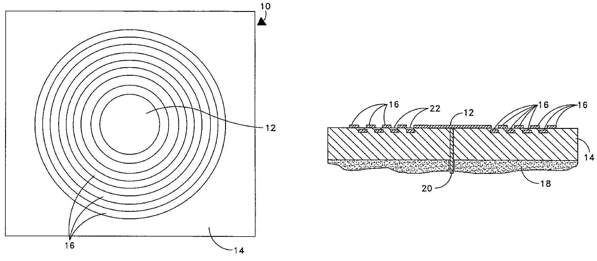
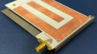
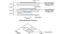
The figure depicts a monopole microstrip antenna according to the invention. The antenna includes an electrically conductive central disk on the top surface of a dielectric substrate and an electrical ground plane on the bottom of the substrate. The central disk is connected to a coaxial probe feed. The antenna also includes concentric electrically conductive rings having various diameters. Some rings are on the top surface of the dielectric substrate; other rings are embedded within the substrate. The diameters of the disk and rings are chosen to suit the desired frequency range of the antenna. The number of rings (typically at least five or six) is chosen to obtain the desired bandwidth: in general, the bandwidth increases with the number of rings.
Each ring on the surface of the substrate overlaps the neighboring ring(s), and the innermost ring overlaps the central disk. The depths of the embedded rings and the amounts of overlap are chosen, in consideration of the permittivity of the substrate material and the desired frequency range, to obtain the amounts of capacitance at the gaps needed to produce a radially traveling wave of current. Proceeding radially outward from the central disk, the capacitance at each gap is made smaller than that of the preceding gap so as to obtain a greater impedance by an amount chosen to obtain the desired radial taper. If the capacitances are chosen properly, then at the outer edge of the outer ring, there remains little energy for an electric-current wave to be reflected back toward the coaxial probe feed to produce a standing wave.
This work was done by David A. Tonn of the Naval Research Laboratory. For more information, download the Technical Support Package (free white paper) at www.defensetechbriefs.com/tsp under the Physical Sciences category. NRL-0007
This Brief includes a Technical Support Package (TSP).
Traveling-Wave Wide-Band Microstrip Antennas
(reference NRL-0007) is currently available for download from the TSP library.
Don't have an account?
More From SAE Media Group
Aerospace & Defense Tech Briefs
Shape-Shifting Origami Could Help Antenna Systems Adapt On-the-Fly
Tech Briefs
High-Aperture-Efficiency Horn Antenna

Tech Briefs
E-Textile Antenna Tuning Stitches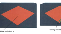

Tech Briefs
Finned-Ladder Slow-Wave Circuit for a TWT
Tech Briefs
New Wireless System for Greater 5G Access
Aerospace & Defense Tech Briefs
Co-Prime Frequency and Aperture Design for HF Surveillance, Wideband Radar Imaging, and Nonstationary Array Processing


Aerospace & Defense Tech Briefs
From DC to Daylight — How Innovations in Microwave Absorbers Shield the Warfighter

Tech Briefs
Electric Nanoscale Device Sees Through Walls
Off-Highway Engineering
Filtering out Common Mode Noise with Monolithic EMI Filters
Tech Briefs
Deployable Fresnel Rings


Tech Briefs
Wireless, Wearable Transmitter
Tech Briefs
Aperture-Coupled Thin-Membrane L-Band Antenna

Aerospace & Defense Tech Briefs
New, Portable Antenna Could Help Restore Communication After Disasters
Aerospace & Defense Tech Briefs
Airborne Antenna Considerations for C-Band Telemetry Systems
Aerospace & Defense Tech Briefs
Microstrip Patch Antennas Containing Multi-PBG Structures
Overview
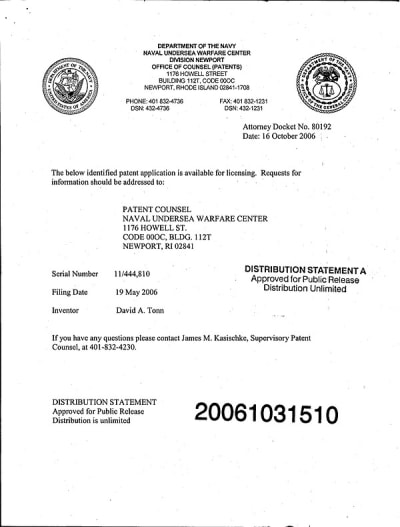
The document pertains to a patent application for a "Wideband Traveling Wave Microstrip Antenna," filed by David A. Tonn and managed by the Naval Undersea Warfare Center, Newport, Rhode Island. The application, identified by Attorney Docket No. 80192, was filed on May 19, 2006, and is available for licensing.
Microstrip antennas have been widely used in various applications; however, they typically suffer from narrow bandwidth limitations. Traditional designs often require stacking or interlacing antennas of different sizes to achieve the desired wideband performance, which can be cumbersome and inefficient. The invention described in this document addresses these issues by introducing a novel approach to antenna design.
The key innovation of this invention is the propagation of a traveling wave of electric current along the microstrip antenna structure, as opposed to the conventional standing wave. This is achieved by incorporating a series of capacitive gaps of specific values into the antenna design. These gaps help tailor the electric current distribution, effectively suppressing the resonant properties that limit bandwidth in traditional antennas.
The proposed microstrip antenna features a "bulls-eye target" structure, consisting of a central disk surrounded by concentrically larger, capacitively coupled annular sections. This configuration is designed to enhance the antenna's bandwidth by minimizing the standing wave effects that typically restrict performance.
The document also includes a statement of government interest, indicating that the invention may be manufactured and used by or for the U.S. government without the payment of royalties. This suggests the potential for significant applications in military and governmental contexts, where advanced communication technologies are critical.
Overall, the invention aims to provide a microstrip antenna with superior bandwidth performance, making it a promising solution for applications requiring wideband capabilities. The document emphasizes the need for improved antenna designs that can operate efficiently across a broader range of frequencies, thereby enhancing communication systems and technologies.
For further inquiries or licensing requests, interested parties are directed to contact the patent counsel at the Naval Undersea Warfare Center. The document is approved for public release, ensuring that the information is accessible to those interested in the advancements in antenna technology.
Top Stories
NewsRF & Microwave Electronics
![]() Microvision Aquires Luminar, Plans Relationship Restoration, Multi-industry Push
Microvision Aquires Luminar, Plans Relationship Restoration, Multi-industry Push
INSIDERAerospace
![]() A Next Generation Helmet System for Navy Pilots
A Next Generation Helmet System for Navy Pilots
INSIDERDesign
![]() New Raytheon and Lockheed Martin Agreements Expand Missile Defense Production
New Raytheon and Lockheed Martin Agreements Expand Missile Defense Production
INSIDERMaterials
![]() How Airbus is Using w-DED to 3D Print Larger Titanium Airplane Parts
How Airbus is Using w-DED to 3D Print Larger Titanium Airplane Parts
NewsPower
![]() Ford Announces 48-Volt Architecture for Future Electric Truck
Ford Announces 48-Volt Architecture for Future Electric Truck
ArticlesAR/AI
Webcasts
Electronics & Computers
![]() Cooling a New Generation of Aerospace and Defense Embedded...
Cooling a New Generation of Aerospace and Defense Embedded...
Automotive
![]() Battery Abuse Testing: Pushing to Failure
Battery Abuse Testing: Pushing to Failure
Power
![]() A FREE Two-Day Event Dedicated to Connected Mobility
A FREE Two-Day Event Dedicated to Connected Mobility
Unmanned Systems
![]() Quiet, Please: NVH Improvement Opportunities in the Early Design Cycle
Quiet, Please: NVH Improvement Opportunities in the Early Design Cycle
Automotive
![]() Advantages of Smart Power Distribution Unit Design for Automotive &...
Advantages of Smart Power Distribution Unit Design for Automotive &...
Energy
![]() Sesame Solar's Nanogrid Tech Promises Major Gains in Drone Endurance
Sesame Solar's Nanogrid Tech Promises Major Gains in Drone Endurance