


Airborne Antenna Considerations for C-Band Telemetry Systems
It is fairly well known within the aerospace community that telemetry is moving from the traditional L-band and S-band frequency ranges up to C-band. It is widely understood that the reason for this push to C-band is two-fold. First, traditional L and S frequency bands have been greatly reduced through reallocation for a variety of reasons by different markets, and second, the bandwidth required for most applications has seen exponential growth. This has not only been seen in military applications, but in civilian aerospace platforms as well.
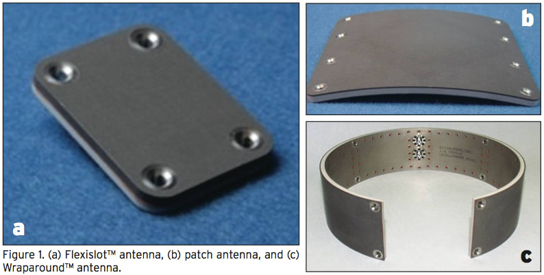 Conformal antennas come in a variety of different shapes, sizes, and configurations, from discrete radiators such as a Flexislot™ (Figure 1a) or a patch antenna (Figure 1b), to arrays such as a Wraparound ™ (Figure 1c). The Flexislot, or patch-style antennas, provide hemispherical coverage, while the Wraparound provides omnispherical.
In telemetry applications, it is usually desirable to cover as much of the radiation sphere as possible to ensure data is received during an abnormal event. This is why the Wraparound configuration is often the optimal solution. There are times, however, where it is not feasible to use a Wraparound. For example, it might not be feasible when there are obstructions on the vehicle that will prevent the utilization of the full circumference, or when the vehicle geometry is non-circular or physically so large that a Wraparound is simply not possible. The use of discrete elements on large geometries is but one consideration that must be taken into account in this transition to C-band telemetry.
Antenna Construction

Vehicle Influence

The effect the vehicle’s geometry has must be considered, regardless of what frequency you are using. It becomes even more important as frequency increases, since fins, wings, or other parasitic structures are electrically larger at C-band than at L- or S-band.
Optimal Number of Elements to Use

It is not always possible to utilize a full-circumference Wraparound, so the next best thing is almost always the two-element case. Certainly, two S-band elements will have far fewer nulls as compared to two C-band elements on the same diameter cylinder. There are limitations on the number of elements that can be utilized for a given configuration.
Positive Effects of Moving to C-Band
Due to the small wavelength, C-band antennas can be made considerably smaller and lighter than their L- and S-band counterparts. In addition, not only does the bandwidth grow proportionally with frequency, but percent bandwidth is actually greater. This means that if you have 100 MHz at S-band, you will have more than 250 MHz at C-band, most likely in the order of 300 to 400 MHz with the same type of design, just scaled up in frequency.
Transition Antennas
While the transition to C-band is taking place, certain areas are still utilizing L-band and S-band. It is therefore highly desirable to have an antenna that will handle all three — L-, S-, and C-band — as using a one-antenna solution simplifies system changeover.
Monopole and dipole antennas naturally provide multi-band performance with regard to voltage standing wave ratio (VSWR); however, only the lowest frequency band provides the desired radiation pattern. A common mistake is utilizing the VSWR solely to evaluate antenna performance. To get the full picture, radiation patterns must also be considered.
There are antennas specifically designed to maintain radiation pattern characteristics over frequency. The radiation patterns are essentially invariant as a function of frequency. The minor differences are actually caused by the ground plane changing in electrical size as we go from 1.4 to 5.25 MHz. The VSWR of the antenna is well under 2:1 over all of the telemetry bands.
Conformal Multi-Band Antennas
There are several ways that both S-band and C-band, or all three (L-, S-, and C-band), can be achieved in a conformal design. Certainly, the simplest is to have a dual-band antenna with two distinct arrays within the same physical package, and two distinct connectors. This would result in possibly having to change to the correct RF connector (band) before use. An alternate approach embeds a diplexer inside a conformal antenna, L- or S-band radiators for legacy systems, and C-band radiators that are all fed through the embedded diplexer. This results in a single-port design. It is also possible to do this with a tri-band configuration of L-, S-, and C-band.
Given that the C-band, L-band, and S-band radiators are optimized for their respective bands, pattern characteristics would be the same and there would be no degradation. This multi-band conformal antenna would require additional space over the legacy L- or S-band antennas. In some cases, it may not be feasible to change the vehicle geometry to accept this larger antenna, but a C-band antenna can always be packaged to replace the lower-frequency legacy units.
Conclusion
There are several antenna considerations when changing from the legacy bands to C-band for telemetry. Choosing the wrong construction type, number of elements, and/or placement can have a major impact on overall performance. While all of the effects cannot be fully mitigated, in most cases, performance can be optimized, which will result in a successful link.
This article was written by David Farr, Chief Executive Officer, and Dr. William Henderson, Chief Technology Officer, at Haigh-Farr, Inc. (Bedford, NH). For more information, Click Here .
More From SAE Media Group
Aerospace & Defense Tech Briefs
A New Concept for Improving the Performance of Electrically Small Antennas
Aerospace & Defense Tech Briefs
Shape-Shifting Origami Could Help Antenna Systems Adapt On-the-Fly
Tech Briefs
Aperture-Coupled Thin-Membrane L-Band Antenna
Aerospace & Defense Tech Briefs
Advances in Millimeter-Wave Isolator Design Launch Manufacturers into Stratospheric Operating Frequencies
Aerospace & Defense Tech Briefs
90° Hybrid Coupled Power Amplifier – Pros and Cons

Tech Briefs
Toroidal Radiation Pattern Patch AntennaAerospace & Defense Tech Briefs
Developing Secondary Surveillance Radar Automated Test Equipment
Aerospace & Defense Tech Briefs
Co-Prime Frequency and Aperture Design for HF Surveillance, Wideband Radar Imaging, and Nonstationary Array Processing
Aerospace & Defense Tech Briefs
Next-Generation Phased Radar Systems Lead to Hardware Improvements

Aerospace & Defense Tech Briefs
NeXtRAD SDR Interface
Aerospace & Defense Tech Briefs
Unmanned Ground Vehicle Communications Relays
Aerospace & Defense Tech Briefs
How to Specify and Select RF Filters
Aerospace & Defense Tech Briefs
EMI Analysis Software Helps Telescope Group Simulate RFI Mitigation
Tech Briefs
Test Strategies to Track Hypersonic Threats
RF & Microwave Technology
Simulation Optimizes Safety and Performance When Integrating an Antenna Onto a Platform
Aerospace & Defense Tech Briefs
New, Portable Antenna Could Help Restore Communication After Disasters

Defense INSIDER
Antenna Design Turns Entire Vehicles into Broadcasting Equipment
Aerospace & Defense Tech Briefs
Pathfinder Radar ISR and SAR Systems: Tactical Eyes for the Warfighter
Aerospace & Defense Tech Briefs
Making AESA Radar More Flexible
RF & Microwave Technology
System Could Detect Concealed Person-Borne Bombs at a Distance
Aerospace & Defense Tech Briefs
Development of an Optically Modulated Scatterer Probe for a Near-Field Measurement System
Aerospace & Defense Tech Briefs
Army and Universities Deploy New Warfighter Communication Technology
Aerospace & Defense Tech Briefs
Terahertz (THz) Radar: A Solution For Degraded Visibility Environments (DVE)
Aerospace & Defense Tech Briefs
Next-Generation Spectrometers for Rapid Analysis of Complex Mixtures

Aerospace & Defense Tech Briefs
Validation of Ubiquitous 2D Radar
Top Stories
INSIDERManufacturing & Prototyping
![]() How Airbus is Using w-DED to 3D Print Larger Titanium Airplane Parts
How Airbus is Using w-DED to 3D Print Larger Titanium Airplane Parts
INSIDERManned Systems
![]() FAA to Replace Aging Network of Ground-Based Radars
FAA to Replace Aging Network of Ground-Based Radars
NewsTransportation
![]() CES 2026: Bosch is Ready to Bring AI to Your (Likely ICE-powered) Vehicle
CES 2026: Bosch is Ready to Bring AI to Your (Likely ICE-powered) Vehicle
NewsSoftware
![]() Accelerating Down the Road to Autonomy
Accelerating Down the Road to Autonomy
EditorialDesign
![]() DarkSky One Wants to Make the World a Darker Place
DarkSky One Wants to Make the World a Darker Place
INSIDERMaterials
![]() Can This Self-Healing Composite Make Airplane and Spacecraft Components Last...
Can This Self-Healing Composite Make Airplane and Spacecraft Components Last...
Webcasts
Defense
![]() How Sift's Unified Observability Platform Accelerates Drone Innovation
How Sift's Unified Observability Platform Accelerates Drone Innovation
Automotive
![]() E/E Architecture Redefined: Building Smarter, Safer, and Scalable...
E/E Architecture Redefined: Building Smarter, Safer, and Scalable...
Power
![]() Hydrogen Engines Are Heating Up for Heavy Duty
Hydrogen Engines Are Heating Up for Heavy Duty
Electronics & Computers
![]() Advantages of Smart Power Distribution Unit Design for Automotive...
Advantages of Smart Power Distribution Unit Design for Automotive...
Unmanned Systems
![]() Quiet, Please: NVH Improvement Opportunities in the Early Design...
Quiet, Please: NVH Improvement Opportunities in the Early Design...