


Development of an Optically Modulated Scatterer Probe for a Near-Field Measurement System
Using near-field radiation patterns to diagnose antenna array defects.
Near-field radiation patterns are useful in diagnosing antenna array defects, measuring far-field antenna patterns where the far-field is prohibitively far, and locating field concentrations in high power microwave applications, which could lead to material breakdown. There are two categories of near-field measurements: direct and indirect. In a direct measurement, the field from the antenna-under-test (AUT) is directly measured by a probe whereas, in an indirect measurement, the field is inferred from the scattering off of a probe that is placed in the near-field.
A simple direct measurement method is to use an open-ended waveguide connected to a network analyzer as the receiver. The near-field is measured by spatially scanning either the AUT or the receiver. Reflections off of background objects can be filtered out in the time domain. For array applications, antennas that are smaller than the open-ended waveguide must be used to achieve spacing less than a half wavelength. An array of time-domain sensors has been demonstrated using loop antennas. The metal transmission line from the probe can perturb the very-near-field making the direct measurement approach less favorable than the indirect measurement approach.
In an indirect near-field measurement, a probe is placed in the near-field and the near-field at the probe is inferred from the scattering off of the probe. These reflections can be measured in either a monostatic or bistatic configuration. In a monostatic configuration, where the transmitting and receiving antenna are both the AUT, the received signal is proportional to the square of the gain of the AUT. Conversely, in a bistatic configuration, where the transmit antenna is the AUT and the receive antenna has a known antenna pattern, the received signal is proportional to the gain of the AUT after normalizing by the antenna pattern of the known receiver. If the scattering strength of the probe is modulated, then the reflected signal off of the probe is amplitude modulated and can be isolated from the unmodulated background signals. The probe can either be modulated mechanically, electrically, or optically. Mechanical modulation is not preferred because it may cause ambiguities in polarization measurements and has a physically limited modulation frequency.
When a probe is electrically modulated, the modulation signal is delivered to the probe on bias lines. These bias lines can cause the maximum amplitude response of the probe to shift in frequency and must be accounted for in the probe design. In an optical modulation system, the active element (typically a photodiode) in the probe is modulated by a laser through a fiber optic cable. The photodiode in an optically modulated probe can operate without a bias voltage, which removes the need for bias lines. Additionally, the fiber optic cable that couples the modulation signal onto the probe has no metal, which reduces the perturbation on the near-field by the probe compared to an electrically modulated probe with metallic bias lines.
To decrease measurement time, the modulated probes can be assembled into arrays. Both electrically and optically modulated probe arrays have been demonstrated. Each probe could be modulated at a different frequency to measure the field at each probe simultaneously to further reduce measurement time.
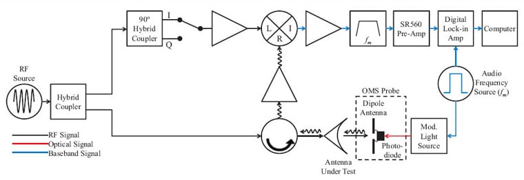
A block diagram of a monostatic, near-field, measurement system with an optically modulated scatterer (OMS) probe is shown in the accompanying figure. An on-off modulated light source delivers an optical signal to the photodiode in the OMS probe that modulates the radar cross-section (RCS) of the OMS probe. The AUT transmits a signal from an RF source into free-space. The return signal consists of a large, unmodulated signal with a small, modulated signal due to the modulation of the RCS of the OMS probe. The unmodulated signal consists of reflections off of objects in the room, including support structures, and from the impedance mismatch between the AUT aperture and free-space.
The combined modulated and unmodulated signal is down-converted and a narrow-band filter eliminates the unmodulated component of the signal. The modulated signal is recorded by a digital lock-in amplifier at the modulation frequency. The amplitude of the measured signal is proportional to the square of the gain of the antenna because the signal is passing through the AUT twice. The OMS probe is raster scanned in a plane in front of the AUT to record the spatial field distribution at a set of discrete points.
This work was done by Mark Patrick, Surface Electronic Warfare Systems Branch, Tactical Electronic Warfare Division; Meredith N. Hutchinson, Photonics Technology Branch, Optical Sciences Division; and J. Brad Boos, Electromagnetics Technology Branch, Electronics Science and Technology Division for the Naval Research Lab. NRL-0071
This Brief includes a Technical Support Package (TSP).
Development of an Optically Modulated Scatterer Probe for a Near-Field Measurement System
(reference NRL-0071) is currently available for download from the TSP library.
Don't have an account?
More From SAE Media Group
Aerospace & Defense Tech Briefs
Frequency Agile Plasmonic Antennas and Sensors
Aerospace & Defense Tech Briefs
Shape-Shifting Origami Could Help Antenna Systems Adapt On-the-Fly

Aerospace & Defense Tech Briefs
Validation of Ubiquitous 2D Radar
Aerospace & Defense Tech Briefs
Terahertz (THz) Radar: A Solution For Degraded Visibility Environments (DVE)
Tech Briefs
Submillimeter-Wave Image Sensor
Aerospace & Defense Tech Briefs
Airborne Antenna Considerations for C-Band Telemetry Systems
RF & Microwave Technology
Simulation Optimizes Safety and Performance When Integrating an Antenna Onto a Platform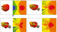
Aerospace & Defense Tech Briefs
Co-Prime Frequency and Aperture Design for HF Surveillance, Wideband Radar Imaging, and Nonstationary Array Processing
Aerospace & Defense Tech Briefs
New, Portable Antenna Could Help Restore Communication After Disasters
Aerospace & Defense Tech Briefs
Streamlined Microcomb Design Provides Control With The Flip of a Switch
Tech Briefs
Laser-Light-Based Accelerometer
NASA Spinoff
Catch the Waves
Photonics & Imaging Technology
Ultra-Narrowband Optical Filters Pushing Boundaries from the UV to the LWIR
ADAS & Autonomous Vehicle Engineering
Testing ADAS Functions in Parallel with EMS Measurement
Aerospace & Defense Tech Briefs
A New Concept for Improving the Performance of Electrically Small Antennas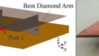
Aerospace & Defense Tech Briefs
Digital Radar Warning Receiver
Aerospace & Defense Tech Briefs
Multi-Agent RF Propagation Simulator
RF & Microwave Technology
System Could Detect Concealed Person-Borne Bombs at a Distance
Tech Briefs
RFID Waveguide, Antenna, and Cavity Sensors
Aerospace & Defense Tech Briefs
Overcoming Performance Limitations of Distributed Brillouin Fiber Laser Sensors
Tech Briefs
Toroidal Radiation Pattern Patch AntennaTech Briefs
Multiplexed Optical Antennas
Aerospace & Defense Tech Briefs
Development of Photoacoustic Sensing Platforms
Tech Briefs
Electric Nanoscale Device Sees Through Walls
Aerospace & Defense Tech Briefs
Multimode Optical Fiber Sensing
Tech Briefs
Free-Space Fiber Optic Laser Rod
Tech Briefs
Quantum Sensor Enables Wide Spectral Coverage
Tech Briefs
Nuclear Radiation-Detecting Device
Aerospace & Defense Tech Briefs
Stepped-Frequency Distributed Radar for Through-the-Wall Sensing
Overview
The document titled "Development of an Optically Modulated Scatterer Probe for a Near-Field Measurement System" presents a novel approach to measuring the near-field patterns of antennas using an optically modulated scatterer (OMS) probe. Authored by Mark Patrick, Meredith N. Hutchinson, and J. Brad Boos from the Naval Research Laboratory, the report outlines the design, implementation, and performance of this measurement system, which is particularly relevant for high-fidelity applications in electronic warfare.
The primary objective of the OMS probe is to minimize the impact of the measurement probe on the near-field of the antenna-under-test. This is achieved through a design that integrates a rectangular dipole antenna with a photodiode, allowing for effective modulation of the radar cross-section (RCS) of the probe. The modulation technique employed helps to distinguish the scattering from the probe itself from background reflections, enhancing measurement accuracy.
The report details the system overview, including a block diagram of the monostatic near-field measurement setup. It discusses the design and performance of two types of photodiodes used in the OMS probe, specifically the Partially Depleted Absorber (PDA) and the Modified Uni-Traveling Carrier (MUTC) photodiodes. The authors provide insights into the optical intensity modulation techniques that are critical for the probe's functionality.
Key results presented in the document include impedance measurements, scattering-amplitude simulations, and near-field pattern measurements of an open-ended waveguide at 15 GHz. The report also addresses system linearity and outlines future developments for the OMS probe, indicating potential enhancements for higher frequency applications.
In summary, this document serves as a comprehensive resource for understanding the advancements in near-field measurement technology through the use of optically modulated scatterers. It highlights the importance of minimizing probe interference in high-fidelity measurements and provides a pathway for future research and development in this field. The findings are significant for applications in electronic warfare and other areas requiring precise antenna characterization.
Top Stories
NewsSensors/Data Acquisition
![]() Microvision Aquires Luminar, Plans Relationship Restoration, Multi-industry Push
Microvision Aquires Luminar, Plans Relationship Restoration, Multi-industry Push
INSIDERRF & Microwave Electronics
![]() A Next Generation Helmet System for Navy Pilots
A Next Generation Helmet System for Navy Pilots
INSIDERWeapons Systems
![]() New Raytheon and Lockheed Martin Agreements Expand Missile Defense Production
New Raytheon and Lockheed Martin Agreements Expand Missile Defense Production
NewsAutomotive
![]() Ford Announces 48-Volt Architecture for Future Electric Truck
Ford Announces 48-Volt Architecture for Future Electric Truck
INSIDERAerospace
![]() Active Strake System Cuts Cruise Drag, Boosts Flight Efficiency
Active Strake System Cuts Cruise Drag, Boosts Flight Efficiency
ArticlesTransportation
Webcasts
Aerospace
![]() Cooling a New Generation of Aerospace and Defense Embedded...
Cooling a New Generation of Aerospace and Defense Embedded...
Energy
![]() Battery Abuse Testing: Pushing to Failure
Battery Abuse Testing: Pushing to Failure
Power
![]() A FREE Two-Day Event Dedicated to Connected Mobility
A FREE Two-Day Event Dedicated to Connected Mobility
Automotive
![]() Quiet, Please: NVH Improvement Opportunities in the Early Design Cycle
Quiet, Please: NVH Improvement Opportunities in the Early Design Cycle
Electronics & Computers
![]() Advantages of Smart Power Distribution Unit Design for Automotive &...
Advantages of Smart Power Distribution Unit Design for Automotive &...
Unmanned Systems
![]() Sesame Solar's Nanogrid Tech Promises Major Gains in Drone Endurance
Sesame Solar's Nanogrid Tech Promises Major Gains in Drone Endurance