


Redesign of composite parts for structural integrity
In the case of composite materials, material properties are vastly dependent on the manufacturing process. While shifting the manufacturing process of a composite part from preimpregnated to a new liquid resin injection process, the Composites Development team at Bombardier Aerospace had to redesign the component to a new set of design allowables. The Integrated Product Development Team (IPDT) was able to quickly provide a turnkey solution that assessed three aspects of airframe engineering: design, materials and processes (M&P), and stress.
The stress substantiation process, led by the team’s stress engineers, required three distinct checks be confirmed: that the global behavior of the surrounding structure remained unaffected, that all local failure modes still exhibited positive margins of safety, and that detail level testing was organized to provide complete substantiation for the certification authorities.

Stress substantiation process
Typically, non-recurring costs associated with high-performance resin transfer molding (RTM) manufacturing preclude small aeronautical production volumes. However, repeating part numbers created a business case where the non-recurring costs were amortized over enough components that the RTM process yielded decreased cost in addition to a shorter cycle time.
The need to size the part to a complete new set of design allowables included a drastic variation in lamina cured ply thickness, as well as notable variations in matrix type failures such as compression after impact and interlaminar shear and tensile stress. As a starting point, both the material and process were qualified and allowables were readily available.
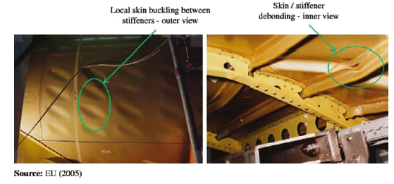
The first consideration while redesigning a component is to ensure the redesigned structure behaves identically to the baseline. Fuselage structures are simply thin skin sheets supported by stiffening members. These members serve two major roles: they provide some area to the fuselage cross-section to carry loads, and they provide support to the skin and prevent it from buckling. For thin sheets subjected to shear or compressive loading, the loads at which the plates buckle are much lower than the material strength.
To ensure that the global modes were still met, buckling analysis was performed using FEA. While beam theory can provide insight on the general behavior of the structure, buckling is an Eigenvalue problem that is far too complex when applied to large structures to be solved analytically. Linear buckling analysis using commercial finite element codes provides a means to correctly evaluate the structure and determine the most critical buckling modes.
The strategy was to use detailed finite element models (FEMs) of sections of the baseline fuselage that were affected by the redesign and subject them to unitary compressive, shear, and combined loading. By subsequently substituting in the FEM the laminate of the baseline design with that of the redesigned component, and re-evaluating the first eigen modes, it is possible to confirm that the redesigned component does not change the modes in which the structure buckles, and that the associated buckling loads are unaffected.
Local failure modes
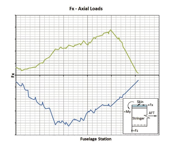
The approach taken for pre-sizing the redesigned part was to reuse as much of the work already completed for sizing the baseline as possible. In sizing reports for skin and stringer panels, it is customary to present shear-bending-axial force (VMA) plots and assess the load levels within the structure and confirm the extracts from the global FEM are coherent.
With a standard plot of envelope axial force along the length of the fore fuselage, it is possible to notice the maximum positive value is slightly larger due to the effect of pressurization when compared to the compressive loads. With the transverse shear loads in a stringer positioned at the window belt, it is possible to notice the window cutouts where large values are obtained, as well as the fore passenger door on the left hand of the plot.
Having defined that the redesigned component was to be subjected to the same loading as the baseline, it was possible to use the plots to extract the most critical load cases. The three maximum and three minimum values of each axial, transverse shear, and bending moment load were determined. These values correspond to combinations of fuselage station (FS)—i.e., position along the fuselage length—and load case and the associated selection criteria. Consistent loading was subsequently extracted for the 18 most critical FS/load case combinations and was used to size the components.
The beam loads subsequently need to be decomposed and distributed to compute the numerous margins of safety associated with the different allowables. This includes primarily laminate strength and local stability of the web and flanges. For this, composite beam theory is used.
The essence of the methodology relies on the fact that equivalent beam rigidities for axial, shear, and bending moments were used to calculate beam strains. These were then used to evaluate the strains at multiple locations along the member cross-sections. These calculated strains were compared against strain allowables for laminate strength. Plate running loads at various locations along the cross-section were also evaluated and compared against buckling allowables or crippling.
The methodology was easily implemented using procedural programming. This contributed to the quick turnaround as multiple iterations of various laminates could be evaluated without the need for a complex analysis to be recomputed. Following inputs from design and manufacturing, a laminate was defined that incorporated requirements for ease of manufacturing. The laminate defined presented little to no fiber deviation and increased drapability while still meeting all stress margins of safety.
While the substantiation methodology is insufficient for the initial design of airframe structures due to the lack of prior knowledge, it does allow for turnkey solutions to be implemented efficiently at all stages of program development. Most importantly, this redesign approach is not associated with the customary exponential cost increase of late changes to projects. This was possible only through prior knowledge of both the new manufacturing process and the current baseline design.
This article is based on SAE International technical paper 2013-01-2328 by Jean-Philippe Lachance and Jean-Evrard Brunel of Bombardier Aerospace.
More From SAE Media Group
Aerospace & Defense Tech Briefs
The Influence of Material Processing on the Performance of Composite Parts
Aerospace Manufacturing and Machining INSIDER
Can This Self-Healing Composite Make Airplane and Spacecraft Components Last for Centuries?
Aerospace & Defense Tech Briefs
Measuring Propellant Stress Relaxation Modulus Using Dynamic Mechanical Analyzer
Aerospace & Defense Tech Briefs
Ruggedizing Coaxial and Fiber Optic Cable Assemblies from Mechanical Strain

Aerospace & Defense Tech Briefs
Advances in Adhesive Joining of Structural Components Focus of New Book from SAE International
Aerospace & Defense Tech Briefs
Multi-Scale Analysis of Deformation and Failure in Polycrystalline Titanium Alloys Under High Strain Rates
Aerospace & Defense Tech Briefs
Spectrum Fatigue of 7075-T651 Aluminum Alloy Under Overloading and Underloading
Aerospace & Defense Tech Briefs
Multifunctional Shear Pressed CNT Sheets for Strain Sensing and Composite Joint Toughening
Tech Briefs
Self-Healing, Recyclable, Shape Memory Polymers
Aerospace & Defense Tech Briefs
Computer Simulation’s Role in Advancing Composite Aircraft Structures
Aerospace & Defense Tech Briefs
Enabling high-strength composites to reach their full potential
Tech Briefs
Cord Tension Measurement Device
Aerospace & Defense Tech Briefs
Cold Spray Technology

Aerospace & Defense Tech Briefs
Sensing Applied Load and Damage Effects in Composites with Nondestructive Techniques
Aerospace & Defense Tech Briefs
Molecular Engineering for Mechanically Resilient and Stretchable Electronic Polymers and Composites
Tech Briefs
Origami-Inspired Material Softens Impact Forces
Aerospace & Defense Tech Briefs
Unlocking the Power of Ceramic Matrix Composites
Aerospace & Defense Tech Briefs
Sandwich Cores for the Future
Aerospace & Defense Tech Briefs
Industry Invited to Participate in AeroTech Aerospace and Defense Technical Program

Aerospace & Defense Tech Briefs
WIAMan
Aerospace & Defense Tech Briefs
Simulating Thermal Expansion in Composites with Expanded Metal Foil for Lightning Protection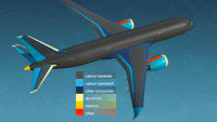
Aerospace & Defense Tech Briefs
Thermal Simulation and Testing of Expanded Metal Foils for Lightning Protection
Aerospace & Defense Tech Briefs
SAE International Issues First Technical Standards for Aerospace Additive Manufacturing
Aerospace & Defense Tech Briefs
Robotic Rotational Molding Creates New Opportunities for Military and Aerospace Applications
Aerospace & Defense Tech Briefs
Streamlining Advanced Composites Testing
Aerospace & Defense Tech Briefs
Blast-Induced Acceleration in a Shock Tube
Aerospace INSIDER
Air Force Explores Use of Thermoplastic Fin for F-16
Top Stories
NewsSensors/Data Acquisition
![]() Microvision Aquires Luminar, Plans Relationship Restoration, Multi-industry Push
Microvision Aquires Luminar, Plans Relationship Restoration, Multi-industry Push
INSIDERRF & Microwave Electronics
![]() A Next Generation Helmet System for Navy Pilots
A Next Generation Helmet System for Navy Pilots
INSIDERWeapons Systems
![]() New Raytheon and Lockheed Martin Agreements Expand Missile Defense Production
New Raytheon and Lockheed Martin Agreements Expand Missile Defense Production
NewsAutomotive
![]() Ford Announces 48-Volt Architecture for Future Electric Truck
Ford Announces 48-Volt Architecture for Future Electric Truck
INSIDERAerospace
![]() Active Strake System Cuts Cruise Drag, Boosts Flight Efficiency
Active Strake System Cuts Cruise Drag, Boosts Flight Efficiency
ArticlesTransportation
Webcasts
Aerospace
![]() Cooling a New Generation of Aerospace and Defense Embedded...
Cooling a New Generation of Aerospace and Defense Embedded...
Energy
![]() Battery Abuse Testing: Pushing to Failure
Battery Abuse Testing: Pushing to Failure
Power
![]() A FREE Two-Day Event Dedicated to Connected Mobility
A FREE Two-Day Event Dedicated to Connected Mobility
Automotive
![]() Quiet, Please: NVH Improvement Opportunities in the Early Design Cycle
Quiet, Please: NVH Improvement Opportunities in the Early Design Cycle
Electronics & Computers
![]() Advantages of Smart Power Distribution Unit Design for Automotive &...
Advantages of Smart Power Distribution Unit Design for Automotive &...
Unmanned Systems
![]() Sesame Solar's Nanogrid Tech Promises Major Gains in Drone Endurance
Sesame Solar's Nanogrid Tech Promises Major Gains in Drone Endurance