


Improved Accuracy of Computational Fluid Dynamics Calculations
Grid adaptation technique improves the accuracy of engineering predictions regarding air vehicle performance.
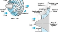
Understanding how air flows over the surfaces of an air vehicle can help AFRL designers maximize the vehicle's performance and minimize its cost. AFRL scientists recently developed a tool that improves the accuracy of airflow simulations that result from computational fluid dynamics (CFD) calculations. As part of a Small Business Innovation Research effort, AFRL collaborated with Combustion Research and Flow Technology (CRAFT), Inc., to develop the tool for use with unstructured CFD programs. The new tool uses the solver's initial solution to determine where grid points should be added or removed within the CFD mesh, a process which then improves the solver's solution in a second—and any subsequent—iteration. This enhanced accuracy improves AFRL's ability to support the warfighter with lower-cost, higher-value designs.

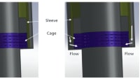
Regardless of whether a grid is unstructured or structured, the initial placement of points in the grid is not necessarily optimal, and therefore, the CFD solution may not very accurately model physical reality. AFRL's new CFD tool addresses this shortcoming by using the initial CFD solution to determine where grid points should be located, an approach that improves the accuracy of subsequently executed solutions. To minimize the time required to modify the location of grid points, as well as enable the processing of arbitrarily large problems, the AFRL/CRAFT team focused its enhancement efforts on making the adaptation process run in parallel on multiple processors. To demonstrate the new capability, the scientists modeled a gaseous hydrogen valve with the plug set at a 52% open position (see figure on previous page). The pressure drop across the valve was 2600 psi, a drop that produces an underexpanded, annular jet at the nozzle throat, between the plug and the valve seat. The complex flowpath leads to formation of a large secondary flow and highly turbulent region in the exhaust duct downstream of the valve seat. The figure, which depicts a cross section of the CFD mesh and the resulting CFD Mach number contours, illustrates the improvement in jet definition with mesh adaptation. On the original mesh (image a), these structures are diffused and even exhibit some unsteady character; after two adaptations (image b), five distinct shock cells (displayed in red) are observable in the annular jet.Regardless of whether a grid is unstructured or structured, the initial placement of points in the grid is not necessarily optimal, and therefore, the CFD solution may not very accurately model physical reality. AFRL's new CFD tool addresses this shortcoming by using the initial CFD solution to determine where grid points should be located, an approach that improves the accuracy of subsequently executed solutions. To minimize the time required to modify the location of grid points, as well as enable the processing of arbitrarily large problems, the AFRL/CRAFT team focused its enhancement efforts on making the adaptation process run in parallel on multiple processors. To demonstrate the new capability, the scientists modeled a gaseous hydrogen valve with the plug set at a 52% open position (see figure on previous page). The pressure drop across the valve was 2600 psi, a drop that produces an underexpanded, annular jet at the nozzle throat, between the plug and the valve seat. The complex flowpath leads to formation of a large secondary flow and highly turbulent region in the exhaust duct downstream of the valve seat. The figure, which depicts a cross section of the CFD mesh and the resulting CFD Mach number contours, illustrates the improvement in jet definition with mesh adaptation. On the original mesh (image a), these structures are diffused and even exhibit some unsteady character; after two adaptations (image b), five distinct shock cells (displayed in red) are observable in the annular jet.
As a result of this enhanced capability, scientists can produce more accurate predictions of air vehicle design performance and reduce design options prior to initiating an expensive build and test process. In addition, engineers can use the same technology to assess existing air vehicles, complementing wind tunnel test efforts designed to improve vehicle performance.
Ms. Melissa Withrow (Azimuth Corporation) and Dr. Matt Grismer, of the Air Force Research Laborator y's Air Vehicles Directorate, wrote this article. For more information, visit http://www.afrl.af.mil/techconn_index.asp . Reference document VA-H-06-04.
More From SAE Media Group

Aerospace & Defense Tech Briefs
SparkJet Actuators for Controlling Flows

Tech Briefs
Device Eliminates Vortices and Vibration
Medical Design Briefs
The Lee Company Inc. Acquires TTP Ventus Limited

Tech Briefs
Supersonic Spike Diffuser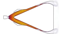

Aerospace & Defense Tech Briefs
Thermal Design and Analysis of a Rocket-Engine TAN Injector
Tech Briefs
Device for Measuring Low Flow Speed in a Duct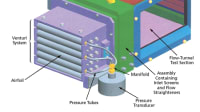

Tech Briefs
Soft Components for Soft Robotics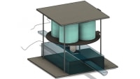
Tech Briefs
Vortobots
Aerospace & Defense Tech Briefs
Some Advances in Reducing Drag and Suppressing Convection
Tech Briefs
Flow-Concentrating Supersonic Gas/Liquid Nozzles

Tech Briefs
Novel Design of an Orifice Control Element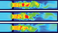
Medical Design Briefs
Product Focus: Pumps/Valves
Motion Design
Designing Smart Solutions for Gas Flow Devices
Off-Highway Engineering
Schaeffler Optimizes Rolling Bearings for Hydraulic and Axle Drives
Motion Design INSIDER
Nimble Dimples: Agile Underwater Vehicles Inspired by Golf Balls
Tech Briefs
Probes for Measuring Pressures in Flowing Gases
Aerospace & Defense Tech Briefs
Approximating the Material Stresses and System Requirements for Hypersonic Flight
Air Force Research Laboratory Technology Horizons
AFRL Finding Ways to Decrease Unmanned Air Vehicle Costs

Air Force Research Laboratory Technology Horizons
AFRL Proves Feasibility of Plasma Actuators
Top Stories
INSIDERDefense
![]() New 3D-Printable Nanocomposite Prevents Overheating in Military Electronics
New 3D-Printable Nanocomposite Prevents Overheating in Military Electronics
Technology ReportSoftware
![]() Talking SDVs and Zonal Architecture with TE Connectivity
Talking SDVs and Zonal Architecture with TE Connectivity
NewsDesign
![]() 2026 Nissan Sentra Review: Putting the Pieces Together
2026 Nissan Sentra Review: Putting the Pieces Together
INSIDERDesign
![]() New Defense Department Program Seeks 300,000 Drones From Industry by 2027
New Defense Department Program Seeks 300,000 Drones From Industry by 2027
INSIDERDefense
![]() Anduril Completes First Semi-Autonomous Flight of CCA Prototype
Anduril Completes First Semi-Autonomous Flight of CCA Prototype
INSIDERDefense
Webcasts
Automotive
![]() SAE Automotive Podcast: Solid-State Batteries
SAE Automotive Podcast: Solid-State Batteries
Manufacturing & Prototyping
![]() SAE Automotive Engineering Podcast: Additive Manufacturing
SAE Automotive Engineering Podcast: Additive Manufacturing
Defense
![]() A New Approach to Manufacturing Machine Connectivity for the Air Force
A New Approach to Manufacturing Machine Connectivity for the Air Force
Software
![]() Optimizing Production Processes with the Virtual Twin
Optimizing Production Processes with the Virtual Twin
Automotive
![]() EV and Battery Thermal Management Strategies
EV and Battery Thermal Management Strategies
Aerospace
![]() How Packet Digital Is Scaling Domestic Drone Battery Manufacturing
How Packet Digital Is Scaling Domestic Drone Battery Manufacturing