Approximating the Material Stresses and System Requirements for Hypersonic Flight

The flow fields around a flight vehicle at hypersonic speeds are markedly different from those at both subsonic and supersonic speeds. The hypersonic regime is not at a discrete speed but evolves over a continuum as speed increases, but is generally defined as a speed of Mach 5 or higher. The flow fields around a vehicle cause the resultant high temperatures and high heat fluxes for the flight system/materials during hypersonic flight, and these stressors in hypersonic flight are called “The Heat Barrier.” Real gas effects come into play at hypersonic speeds due to these high temperatures, and include vibrational excitation, dissociation, chemical reactions, and ionization. The underlying cause of this change in the flow fields is that the pressure waves created by the body moving through the atmosphere can only travel at the speed of sound.
It is these pressure waves that travel ahead of the body and shape the flow field far from the body of a subsonic vehicle. At hypersonic speeds, the pressure waves have virtually no time to propagate away from the flight body, creating a condition where the pressure waves stack up very close to the flight body. These stacked up pressure waves form a bow shock very close to the flight body, where viscous heating occurs due to shear forces. These high-temperature gases close to the flight body surface lead to the high heat fluxes and high surface temperatures found in hypersonic flight.
The flow fields near the surface are plagued by nonequilibrium and/or chaotic thermodynamic conditions, where the temperature of the surfaces affects the flow field, thus affecting the temperature and so on. The problem of hypersonic flight is an exceedingly complex dynamic process, in that there is an interplay among the chemical changes to the surfaces, the changes in emissivity, surface temperatures, impact damage, and the flow fields, which all interact and feed back on one another. Although computer modeling has made great advances, this interplay cannot be accurately modeled currently. Also, there are no experimental facilities that can simulate all the flow conditions that are experienced during hypersonic flight. Even in cases where the flight conditions can be achieved, it is well known that the acoustic noise from the walls of the wind tunnel can alter the formation of shock waves. This results in increased turbulent flow on the different areas of the surfaces being tested depending on how these acoustic waves interfere, constructively or destructively. This can increase turbulence and lead to greater heat transfer (aerodynamic heating) than what would be found in the same structure in an atmospheric test flight.
Manufacturing variations can also lead to changes in the gas flow over surfaces and alter localized aerodynamic heating creating unexpected hotspots. The ablative heat shield tiles on the shuttle had to be hand mounted to insure an exacting degree of 2 uniformity. It was found that the protrusion of a single tile by as little as 1 mm would result in distortions of the shock wave downstream and resulted in unexpected hot spots that caused significant changes in the ablation rates of the tiles.
This should make clear that the conditions along the surface of a hypersonic body are specific to that object’s geometry and defects. Further, even the ablation process itself can lead to sufficient structural changes that alter the gas flow over the surface, thereby altering the deposition of heat to the structure, which in turn alters the ablation rates, thus requiring intensive computer modeling and, in particular, actual flight testing to truly evaluate how a particular design will perform.
The Mach Cone
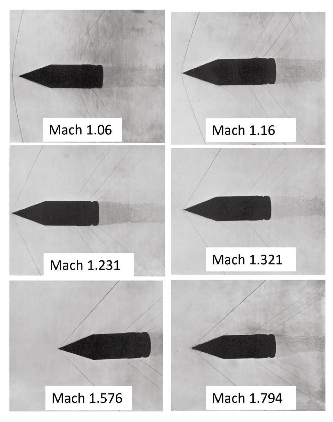
In 1936, Maccoll conducted experiments to image the Mach cone of antitank rounds traveling at supersonic velocities. Some of the photographs captured by Maccoll are shown in Figure 1. In the image on the top left, labeled Mach 1.06, the bow shock wave can be clearly observed to be out in front (left) of the point of the anti-tank round. There is a significant separation between the shock wave and the tip of the round. Also, the large radius of curvature of the shock wave results in a large volume of air in between the anti-tank round and the shock wave. In the next photo (top right), labeled Mach 1.16, the bow shock appears very close to the apex of the round. In addition, the radius of curvature has significantly decreased in comparison with Mach 1.06 and the shock wave has taken on the shape of a very blunt cone. With the progression to higher speeds, the angle of the bow shock, to the axial direction of the round, continues to decrease from Mach 1.231 to Mach 1.321 and then to Mach 1.576. Finally, at Mach 1.794, we see the smallest angle of the bow shock to the round’s axial direction.
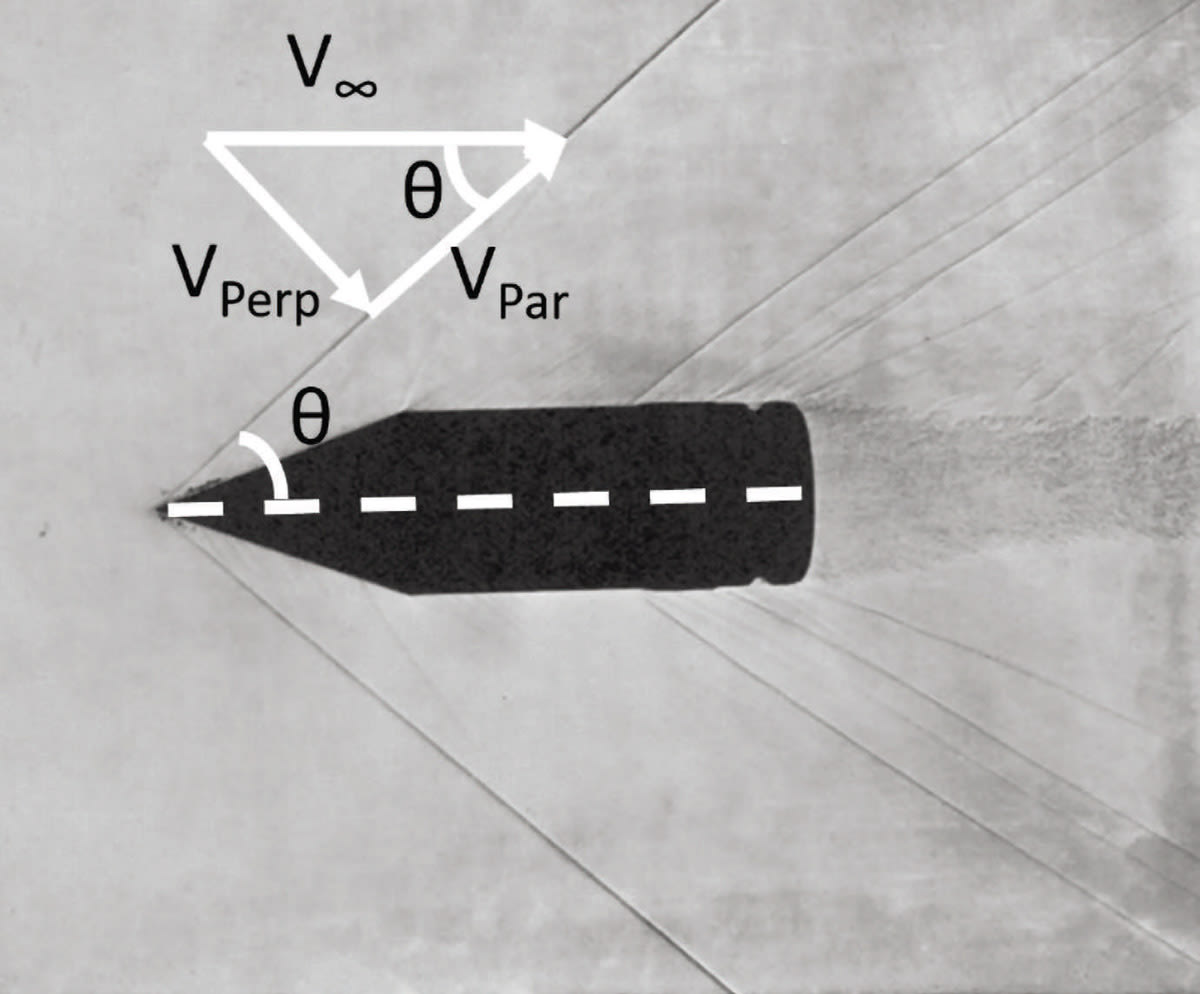
Figure 2 shows the annotated photo of the anti-tank round at Mach 1.794. The tilting angle (θ) of the bow shock is with respect to the centerline (dashed white line) of the anti-tank round. The components of the free stream velocity (V∞) are shown, where VPerp is the component perpendicular to the shock front and VPar is the component along or parallel to the shock front.
The angle at which the perpendicular component (VPerp) is equal to Mach 1 is the angle at which the Mach cone or shock front forms. In Eq. 1, the angle (θ) of the Mach cone can be solved for a given free stream velocity (V∞), where VPerp is set to 1. This equation, Eq. 1, for the shock front cone angle is applicable to slender bodies: θ= sin-1 (Vperp/V∞).
For the case of the projectile in Figure 2 with a free stream velocity of Mach 1.794, the predicted Mach cone angle is 49.2°. From a cursory visual inspection, one can readily see that this is in reasonable agreement with the experimental angle of the shock wave in Figure 2.
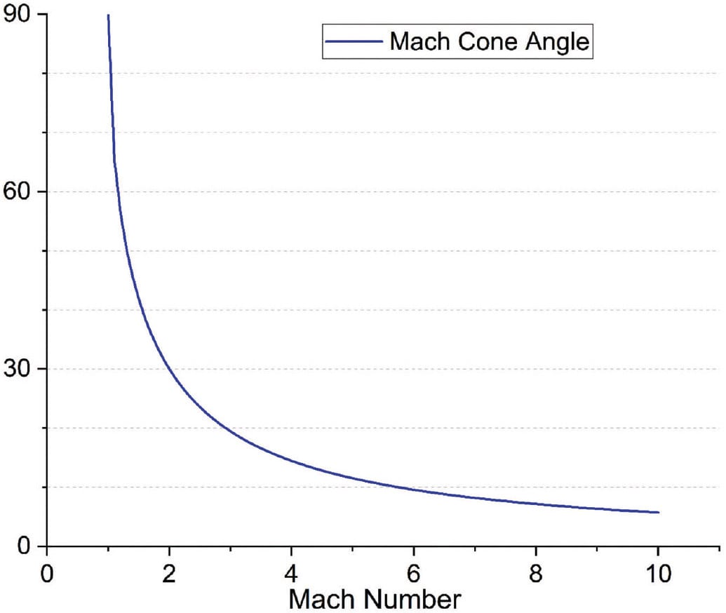
This decreasing tilt of the Mach cone with increasing free stream velocity is a major factor in driving the characteristics of hypersonic flight, specifically aerodynamic heating. In Figure 3, a plot of Eq. 1 is shown where the x-axis is the Mach number and the y-axis is the respective Mach cone angle (as shown in Figure 2). As hypersonic speeds are attained, the Mach cone angle becomes very small. For a slender body at Mach 5, the Mach cone angle is predicted to be 11.5°. Clearly at the speed of Mach 5, the Mach cone or shock wave will come very close to the surface of the projectile. This causes a trapped region of gas between the shock wave, where gases are decelerated (heated), and the body of the projectile. The stagnation temperature of this gas tends to be very high at hypersonic speeds. The close proximity of these hot gases, and the resultant heat load, to the flight vehicle is the main material and engineering challenge to hypersonic flight.
Aerodynamic Heating
The ideal gas law consists of three main components, where P is the pressure; V is the volume; n is the number of mols; R is the ideal gas law constant, which is the product of the Boltzmann constant and Avogadro’s number; and finally T is the temperature, represented as PV = nRT. The ideal gas law is derived by assuming a gas has 3 degrees of freedom. Shock-induced heating that occurs during hypersonic flight causes the gases to deviate from this law. The underlying cause is the fact that R is dependent on Boltzmann’s constant. Implicit in the calculation of Boltzmann’s constant are the degrees of freedom that a gas molecule has and consequently the number of quantum mechanical energy states available (or the density of states) the gas molecules can occupy.
The shock-induced temperatures and frictional forces that gases undergo during hypersonic rates raise the kinetic energy high enough to enable additional degrees of freedom, specifically the vibrational modes of the diatomic gas are activated. This means that the heat capacity of the gas is not constant but changes due to the additional energy states available. These vibrational states are initially activated in the Mach 3 to 4 range and lead to measurable deviations from the ideal gas law at hypersonic speeds. This increased ability to carry heat consequently leads to an increased heat transfer to the flight body.
In the Mach 9 range at altitudes in the lower stratosphere (~10,000 m) range, oxygen dissociation begins to take place. This oxygen dissociation is also referred to as one of the “thermochemical effects.” At speeds around Mach 16, another thermochemical effect begins to take place, nitrogen dissociation. At this point, both oxygen and nitrogen radicals can land on surfaces and cause thermochemical-induced reactions with the surfaces. Finally, at speeds near Mach 30, plasma will begin to form a conductive sheath around the flight object. This plasma sheath has sufficient electrical conductivity to act as a Faraday cage, leading to the blocking of both the transmission and receipt of electromagnetic communication signals (i.e., a “blackout”).
Erosion
At hypersonic speeds, the kinetic energy in a collision between vehicle surfaces and dust/raindrops can result in erosion due to impact damage. A theoretical equation for the damage threshold velocity from is represented as: Vthreshold =(K1C2cR/ρw2cw2dw) 1/3. The fracture toughness is KIc, the Rayleigh surface wave speed cR, density of water ρw, the compressive wave speed of water cw = 1,500 m/s, and the diameter of the raindrop dw = 1.5 mm.
Monteverde et al. examined the mechanical properties of zirconium diboride–silicon carbide (SiC) matrix composites. The density of the composites was found to be between 5.51 and 6.09 g/cm3 dependent on the SiC weight percent (5 to 20 wt). The modulus E was found to be between 518 and 477 GPa, the fracture toughness was between 4.49 and 5.42 MPaM1/2, the hardness was between 19.3 and 21.7 GPa, and Poisson’s ratio was between 0.103 and 0.117.
It should be noted that at these high Mach numbers, as a droplet transits the shock wave, it will tend to dissipate due to sheer forces and heating. Droplets will also tend to become elongated perpendicular to the direction of motion, becoming disc-like and spreading any force out over a larger area thus reducing damage. Additionally, the angle between the water disc and the projectile’s surface will affect the area the impacting disc is spread out over as well as reduce the normal component of the impact force. This indicates that a leading edge that is very “sharp” will suffer less impact damage.
Conclusion
The challenges associated with hypersonic flight are significant in that the drag forces, temperatures, and heat flux put large demands on materials. First and foremost is managing the exposure to high temperatures that will be in excess of 1,000 °C. The high heat flux to the flight body can result in very high temperatures of the entire vehicle during flight. Mechanisms to carry away heat, such as increased emissivity of leading-edge materials, should be explored. The use of cooling in the form of water vaporization may be a route that can be used to increase rocket fuel efficiency and provide a mechanism for throttling a solid fuel rocket. As the effects of erosion are unavoidable at hypersonic speeds, the use of materials with high Young’s moduli could mitigate this effect.
This article was written by Thomas Parker, Materials Engineer, U.S. Army Research Lab. It has been edited. For more information, visit here .
Top Stories
INSIDERManufacturing & Prototyping
![]() How Airbus is Using w-DED to 3D Print Larger Titanium Airplane Parts
How Airbus is Using w-DED to 3D Print Larger Titanium Airplane Parts
INSIDERManned Systems
![]() FAA to Replace Aging Network of Ground-Based Radars
FAA to Replace Aging Network of Ground-Based Radars
NewsTransportation
![]() CES 2026: Bosch is Ready to Bring AI to Your (Likely ICE-powered) Vehicle
CES 2026: Bosch is Ready to Bring AI to Your (Likely ICE-powered) Vehicle
NewsSoftware
![]() Accelerating Down the Road to Autonomy
Accelerating Down the Road to Autonomy
EditorialDesign
![]() DarkSky One Wants to Make the World a Darker Place
DarkSky One Wants to Make the World a Darker Place
INSIDERMaterials
![]() Can This Self-Healing Composite Make Airplane and Spacecraft Components Last...
Can This Self-Healing Composite Make Airplane and Spacecraft Components Last...
Webcasts
Defense
![]() How Sift's Unified Observability Platform Accelerates Drone Innovation
How Sift's Unified Observability Platform Accelerates Drone Innovation
Automotive
![]() E/E Architecture Redefined: Building Smarter, Safer, and Scalable...
E/E Architecture Redefined: Building Smarter, Safer, and Scalable...
Power
![]() Hydrogen Engines Are Heating Up for Heavy Duty
Hydrogen Engines Are Heating Up for Heavy Duty
Electronics & Computers
![]() Advantages of Smart Power Distribution Unit Design for Automotive...
Advantages of Smart Power Distribution Unit Design for Automotive...
Unmanned Systems
![]() Quiet, Please: NVH Improvement Opportunities in the Early Design...
Quiet, Please: NVH Improvement Opportunities in the Early Design...

