


Gearshift Actuator Dynamics in a Dual Clutch Transmission
The emergence of tougher environmental and fuel efficient legislations have triggered exploration and advance toward new and better vehicle transmission technologies.

Some emerging transmission technologies have seen a growing trend toward increased drive comfort, fuel efficiency, and low CO2 emission. The most recent additions have been variants or hybrids of the automated mechanical transmission (AMT) including fully automated mechanical transmissions (fAMTs), continuously variable transmissions, hybrid-electric vehicles, and dual clutch transmissions (DCTs).
The AMT variants such as the DCT combine the convenience of an automatic transmission with the high efficiency of a manual transmission by using twin clutches, one for odd-numbered gears and the other for even-numbered gears. This design allows uninterrupted and smooth upshifts or downshifts through the speed ratios without loss of traction, hence no perceptible jolts during gearshifts.

For instance, while the vehicle is meshed with the output shaft by the synchromesh mechanism to engage the odd-numbered gear clutch, as soon as the conditions for an upshift or downshift are met, the even-numbered clutch is engaged simultaneously with the disengagement of the odd-numbered gear clutch in a process similar to the shift overlap function of an automatic transmission.
However, unlike in automatic transmissions, the twin clutches of a DCT are subjected to higher loads due to the overlapping gearshifts, slip control, and more frequent gearshift operations. Precise actuator control during an upshift or downshift allows a seamless torque transfer between the two sub-transmissions.
Engaging with DCT
A DCT can work in two different ways: semi-automatic, when the gearshift process is initiated by the driver by means of a shift paddle/shift lever, or fully automatic, using sophisticated electronics attending to the strategy of the gear ratio selection according to engine regime and the prevailing driving conditions.
Recent studies have focused primarily in the control and modeling of AMTs. Such research was intended to improve numerical modeling for accurate predictions of dynamic responses of such systems during the transmission prototype development and the control system optimization.
However, while conventional transmission technologies are well developed for both passenger and commercial vehicles, the hybrid technologies such as DCTs are still at the emerging development stages, especially in high fidelity refinement of control algorithms for all driving conditions.
There has been some research on the analysis and modeling of a DCT’s dynamic characteristics. However, the methods suggested in several studies are open-loop-based control with experimental calibration. Since a DCT does not have a torque converter, achieving sophisticated torque control under varying driving conditions poses a big challenge.
Among the control approaches for the DCT gearshift seen in most literature, some strategies cannot be optimized without the precise control of the engine and twin clutches, whereas others allow tracking of the output torque trajectories. Although the former approach cannot guarantee the high shift quality, the latter presents challenges in measurement of the output torque directly at output axle.
Current research being done at Western Michigan University is intended to develop a dynamic gearshift actuator and control algorithm for the gearshift quality optimization through accurate prediction of the actuator dynamic responses during the gear change transition.
Gearshift actuation
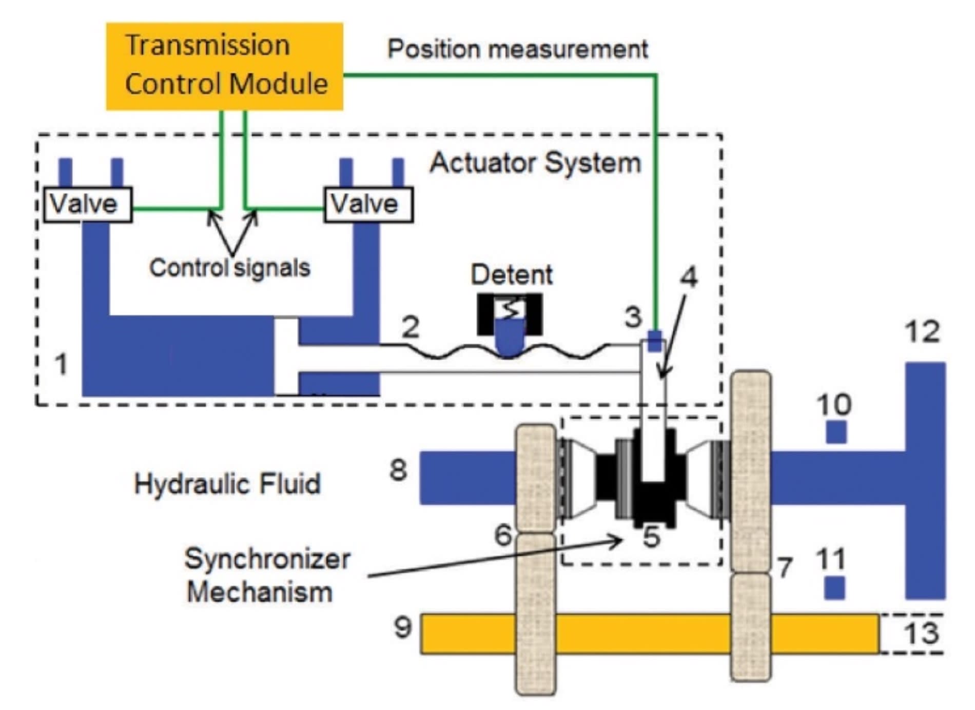
To achieve a smooth launch and a fast gearshift demand in a twin clutch transmission, shift actuation can be controlled electronically by hydraulics using a valve assembly, with a complex maze of passages that distribute pressurized transmission fluid to the actuators inside the transmission.

Electronic transmission management is controlled by the transmission control module (TCM), which calculates optimum gear ratios and controls the actuators to engage gears at the optimal time, increasing driving comfort and decreasing fuel consumption. The TCM initiates a gear change in response to the inputs from the driver, engine, and the gearbox.
Interconnectivity is an important capability of modern transmissions. Vehicle and engine status data are transmitted through the control area network or serial peripheral interface, both of which are international standard intra-vehicle communication networks to the TCM.
Electronic transmission management systems typically operate on an event-driven basis by selecting the gear that provides the optimal torque to meet the prevailing driving conditions with the engine operating in the most favorable map range, such as the range that produces the lowest fuel consumption hence low CO2 emissions.
One of the major benefits of a twin clutch transmission is the shift quality improvement by balancing friction work done by the dual clutches. An overall gearshift quality improvement strategy needs to meet the following objectives: minimization of the mean vehicle deceleration due to traction loss, reduction of the shifting time, and minimization of driveline oscillations resulting from the transmitted torque variations as well as clutch and gearbox operations.
The control parameter adjustment for each shift schedule can be determined in an optimization calculation by means of an empirical model of the shift behavior.
Gearshift control logic
The gearshift control logic determines the optimal time to perform a gearshift during the drive cycle in attaining the best fuel economy. Studies have been conducted to fine-tune the gearshift strategies. Most of these studies have focused predominantly on the vehicle speed, with the engine typically modeled as a mass inertia that accepts throttle angle as the input to produce a mean torque at the crankshaft.
For this research, gearshift logic was constructed in Simulink incorporating a state-flow that drives the actuator based upon the vehicle speed and throttle position. For the actuator control scheme, a decoupled simulation model was established in which the actuator parameters calculated from both physical measurements and FEA such as current, pressure, force, and displacement characteristics were incorporated in the form of look-up tables.
Gearshift quality dynamic models include the synchronizer, selector, and the driveline. The model utilizes the actuator displacement transfer function and solves for the actuator velocity and acceleration both axially and rotationally. The drivetrain consists of component models of the dual clutches, lay-shaft transmission gear-sets, driveshaft, differential, and a vehicle model that incorporates the road load and aerodynamic drag. All synchronizers and gears are modeled as non-compliant elements, which are represented as mass inertias. The input and output shafts are modeled as compliances and are represented by torsion spring-damper assemblies. Clutches and synchronizers are modeled as friction elements with hydraulic pressure as control signals.
Once a gearshift command is launched from the gearshift model based upon the gearshift scheduling logic, the dual clutch controllers are triggered. The dual clutch controllers include the engagement controller, the slip initialization controller, the synchronization controller, the slip start controller, and the slip end controller. The controllers inter-change between each other by triggering the proper control logic in the specific operating phase.
When no gearshift is requested, the engagement controller maintains a high pressure control signal to the hydraulic actuator to maintain the prevailing clutch engagement. Once a gearshift becomes active, the clutches control switches to the slip initialization controller followed by the gearshift actuation.
Engine control
The advent of higher choice of gears in today’s gearboxes allows for increased use of the engine’s power band, which facilitates optimized higher torque output by staying closer to the engine’s peak power, or fuel economy by staying in the most fuel-efficient part of the power band.
However, a responsive engine capable of maintaining the output torque during the gear pre-selection but with an optimized fuel flow to the engine is desirable, which allows the engine to promptly provide increased torque immediately after the gearshift. This is more critical when the gearshift occurs at a juncture when the engine is under low load, hence under relatively low fuel supply that may result in a delay in subsequent increase of the output torque.
A responsive engine is also desirable during a downshift under low load followed by acceleration or when the engine speed is required to promptly match the road speed in a new gear.
One method used to obtain an optimized engine’s power utilization is by adjusting the ignition timing or the moment in which fuel is ignited in the combustion chamber relative to the crankshaft phase. The accelerator pedal provides an input to an engine control unit (ECU), which sets operating parameters of the engine. Additionally, the airflow to the combustion chambers can be increased, which implies optimal air and fuel mixture will be available when the torque increase is required.
The above remedies may be implemented in isolation or concurrently depending on the prevailing vehicle condition. For instance, the vehicle accelerator could be fully on, partially on, or fully off or the vehicle could be driving around a corner, as reported by a steering wheel sensor or a yaw sensor.
The ECU typically implements a mapping between possible accelerator pedal positions and the engine power or torque outputs; hence, a simulated engine torque can be determined from a precalibrated engine map, which is a look-up table with the throttle position and engine speed as inputs and the engine torque as the output. The engine torque output can be characterized as a function of the engine speed and by a change of the throttle angle, which implies that the engine may be mathematically modeled in terms of the throttle angle and the engine angular velocity.
The gearshift process is usually characterized by an abrupt change in vehicle driveline speed leading to the driveline torque interrupt, commonly known as the torque phase. When the gearshift process is completed, the drive shaft torque is recovered to its desired value corresponding to the newly engaged gear ratio, commonly known as the inertia phase.
Occasionally, an overshoot may occur as a result of variations in torque transfer from the torque phase into the inertia phase. This may lead to a perceptible vehicle jerk, which may be noticeable by the vehicle occupants as discomfort. To alleviate this problem, the engine torque reduction has been incorporated alongside the gearshift control. For instance, during an upshift the engine torque controller defines the targeted engine speed spectrum within which the clutch engagement needs to be completed. If the targeted engine speed is too low as compared to the nominal value, it is possible that the engine could be stalled.
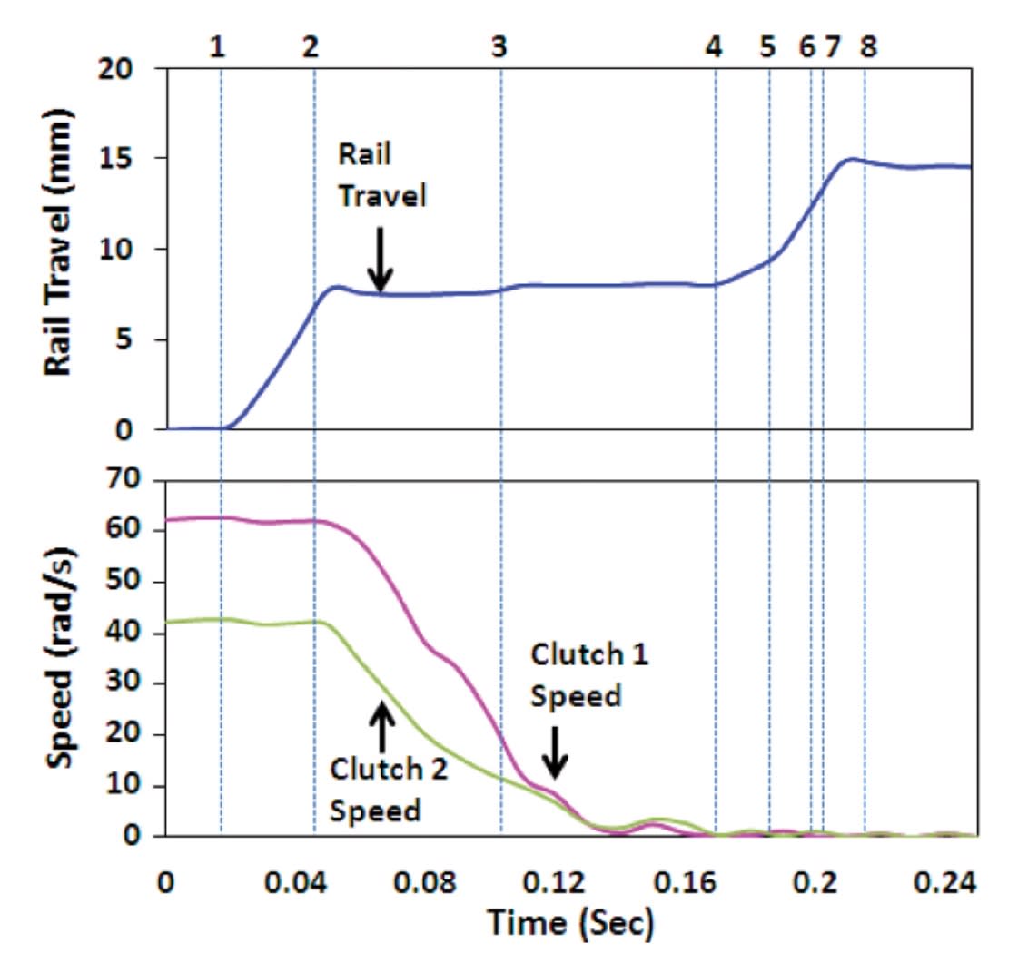
On the other hand, too high of a target engine speed may deteriorate the shift quality. The targeted engine speed is determined by measuring the dual clutch speeds in comparison to the desired gearshift duration. Since the gearshift is usually completed in a short period of time, an assumption of a linear relationship of the engine speed with respect to time can be made.
The engine output torque is interpolated as a function of the throttle angle and the engine speed from the engine map modeled as a look-up table. Once defined, the engine torque can be controlled indirectly by a feedback of a speed tracking error within the model. The desired engine speed can be calculated from the difference between the prescribed maximum engine speed value and the idle speed.
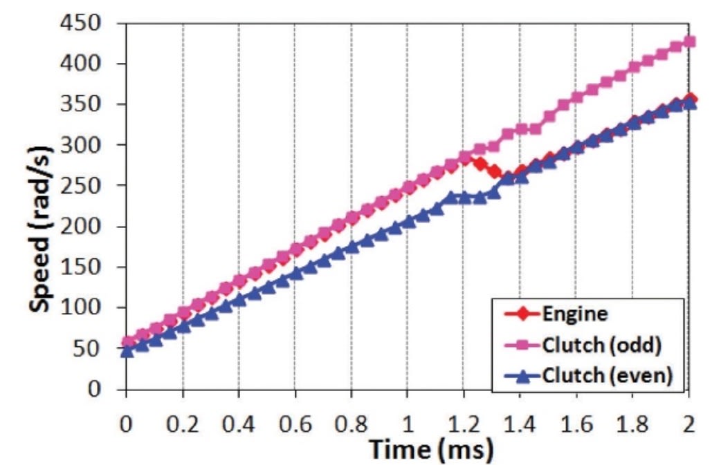
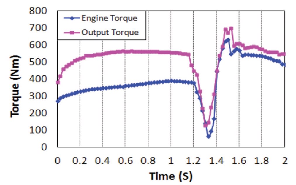
Speed synchronization between the two clutches is completed within 1.0 to 1.5 seconds. Subtle clutch speed oscillations are noticeable after the on-coming clutch engagement. The engine torque is reduced just before the on-coming clutch engagement to reduce shift shocks. This approach provides an effective way for active driveline oscillation damping resulting from the output shaft torque oscillations due to the kinetic energy of the newly engaged gear immediately after the clutch engagement. The damping characteristic also enables attenuation of the engine torque pulsations before being transmitted to the driveline, effectively achieving a smoother gearshift control by reducing torque interrupts during the inertia phase.
During a 1-2 upshift, Clutch 1 is released simultaneously with Clutch 2 engagement; hence, both clutches begin to slip during the shift period. Subsequently, the engine torque is not directly transmitted to the intermediate shaft by the engaged clutch. At the beginning of the shift, the off-going clutch pressure is significantly reduced to the threshold for disengagement, resulting in a drop of the output torque. The output torque is a function of the engine torque, engine speed, gear ratio, and the driveline inertia; hence, controlling the desired engine speed response suppresses the peak torque at the end of the inertia phase.
This article is based on SAE international technical paper 2013-01-9021 by John Manyala, Western Michigan University.
More From SAE Media Group
Automotive Engineering
More Gears, More Challenges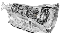
Automotive Engineering
Renault Applies Model-Based Systems Engineering to Dual-Clutch Transmission
Automotive Engineering
Inside Tremec’s Corvette Dual-Clutch Transmission
Off-Highway Engineering
Miserly Power Systems
Off-Highway Engineering
Dual-Clutch Transmission
Automotive Engineering
Powertrain Sensors Add Functions, Help Reduce Wiring
Off-Highway Engineering
FEV Simplifies Off-Highway Electrification
Off-Highway Engineering
Engine Developers Increase Efforts to Decrease Fuel Usage
Automotive Engineering
Making the Torque-Transfer Transition
Off-Highway Engineering
Paccar Announces TX-18 Automated Transmission
Tech Briefs
Offset Compound Gear Inline Two-Speed Drive
Off-Highway Engineering
Reshaping the Mobile-hydraulic Ecosystem
Automotive Engineering
First Drive: 2027 Mercedes-Benz CLA Hybrid
Off-Highway Engineering
Daimler Trucks' Lessons Learned from SuperTruck Program
Off-Highway Engineering
Bigger Processors, Smaller Engines
Automotive Engineering
Gearing EVs for Greater Efficiency
Automotive Engineering
Positioning for Hybrid Growth
Battery & Electrification Technology
Ultracapacitor Solutions to Address Energy-Storage Needs of Vehicles
Off-Highway Engineering
Eaton Unveils DCT for Medium-Duty Trucks and Buses
Automotive Engineering
Dana Opens New Chapter on CVTs
Automotive Engineering
Bosch’s EV Efficiency Upgrade: Continuously Variable Transmissions
Off-Highway Engineering
Transmission Talk: Eaton Discusses Its Portfolio of Commercial Gearboxes
Automotive Engineering
VW Reveals Hot New 10-Speed DSG—and a Cool Dashboard Design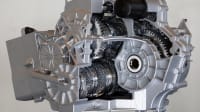
Off-Highway Engineering
Freightliner’s Medium-Duty Makeover
Automotive Engineering
Honda's New 8-Speed DCT Uses a Torque Converter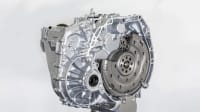
Off-Highway Engineering
Volvo Reveals New VNL with SuperTruck Influence
Off-Highway Engineering
Allison Purpose-Builds More Powerful TerraTran Transmission
Off-Highway Engineering
Komatsu America Adds to Intelligent Machine Lineup
Automotive Engineering
BorgWarner Prepares Manual Gearchange for ADAS Vehicles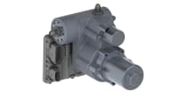
Off-Highway Engineering
Schaeffler Optimizes Rolling Bearings for Hydraulic and Axle Drives
Top Stories
INSIDERManufacturing & Prototyping
![]() How Airbus is Using w-DED to 3D Print Larger Titanium Airplane Parts
How Airbus is Using w-DED to 3D Print Larger Titanium Airplane Parts
INSIDERManned Systems
![]() FAA to Replace Aging Network of Ground-Based Radars
FAA to Replace Aging Network of Ground-Based Radars
NewsTransportation
![]() CES 2026: Bosch is Ready to Bring AI to Your (Likely ICE-powered) Vehicle
CES 2026: Bosch is Ready to Bring AI to Your (Likely ICE-powered) Vehicle
NewsSoftware
![]() Accelerating Down the Road to Autonomy
Accelerating Down the Road to Autonomy
EditorialDesign
![]() DarkSky One Wants to Make the World a Darker Place
DarkSky One Wants to Make the World a Darker Place
INSIDERMaterials
![]() Can This Self-Healing Composite Make Airplane and Spacecraft Components Last...
Can This Self-Healing Composite Make Airplane and Spacecraft Components Last...
Webcasts
Defense
![]() How Sift's Unified Observability Platform Accelerates Drone Innovation
How Sift's Unified Observability Platform Accelerates Drone Innovation
Automotive
![]() E/E Architecture Redefined: Building Smarter, Safer, and Scalable...
E/E Architecture Redefined: Building Smarter, Safer, and Scalable...
Power
![]() Hydrogen Engines Are Heating Up for Heavy Duty
Hydrogen Engines Are Heating Up for Heavy Duty
Electronics & Computers
![]() Advantages of Smart Power Distribution Unit Design for Automotive...
Advantages of Smart Power Distribution Unit Design for Automotive...
Unmanned Systems
![]() Quiet, Please: NVH Improvement Opportunities in the Early Design...
Quiet, Please: NVH Improvement Opportunities in the Early Design...