


Harnessing FPGAs for Beamforming Software Radio Systems
Over the past 20 years, software defined radio techniques have not only revolutionized radar and communications systems, but they have also boosted system performance levels. One of the most widely-deployed and technically challenging operations in these systems is beamforming.

Beamforming is a signal processing technique that utilizes an array of sensors to achieve directionality, increase the strength of transmitted signals and improve the quality of received signals. Beamforming applications span frequencies from sub-audio to light, and encompass a diverse range of critical applications for commerce, industry, government and defense. Systems developers are continuously exploiting new technology to boost performance for specific applications, with significant emphasis on communications and signals intelligence.
Beamforming: Principles and Benefits
For software radio systems, the beamforming sensors are transmit and receive antennas. For receiver systems, the signal arrival delay at each antenna is directly proportional to the path distance from the source. The beamforming process adjusts the gain and phase of each antenna signal to cancel the delay path differences for signals arriving from a particular direction. Aligned signals are then summed together to produce high signal-to-noise reception in the chosen direction.
By adjusting gain and phase in each path, the antenna is electronically “steered” without the need for moving mechanical structures. Examples of software radio applications that use beamforming include direction finding, in which a beamformed antenna can be steered to locate the arrival angle of a signal source. Two or more arrays can be used to triangulate the exact location of the source, which is essential for many signal intelligence and counter terrorism efforts.
In addition to directionality, beamforming also improves reception in so-called “diversity receivers”. The combined signal from multiple antennas boosts the signal-to-noise ratio compared to a single antenna, thus extending the operational range of the receiver system.
Missile detection and countermeasure applications use beamforming to improve tracking of an object allowing for early detection and improved responsiveness. With no moving mechanisms, airborne arrays take full advantage of electronic steering to dramatically improve the range and target resolution. And lastly, beamforming allows spatial frequency sharing for commercial mobile phone carriers by dividing one cell into several beamformed pie-slice sectors that can share the same frequency.
FPGAs — Ideal Beamforming Engines
Each new generation of FPGA delivers new features, higher levels of performance, and reduced power consumption for a given function. The Virtex-6 Series of FPGAs from Xilinx represent a major step, featuring 40 nm silicon technology, over 2000 DSP engines, serial gigabit transceivers with rates up to 11 GHz, fast PCI Express (PCIe) end points, and over 750,000 logic cells.
Because they can implement extreme parallelism with hundreds of DSP blocks operating in parallel, FPGAs are best suited for processing-intensive digital signal processing algorithms, especially like those found in beamforming applications.
Unlike FPGAs, general purpose programmable RISC or DSP processors have a finite set of multipliers, adders, and shift registers in the ALU which must be operated sequentially for each sample. As a result, earlier beamforming systems using RISC and DSP processors have been largely eclipsed by newer FPGA-based designs.
The key signal processing elements for beamforming include digital down conversion, phase and gain adjustments, and summation, all handled by the DSP engines. The PCIe interface provides a fast interface to the system controller for initialization and delivery of beamforming coefficients for gain and phase shifts. The gigabit serial links also can be extremely useful in propagating the beamformed summation across multiple boards for high channel count systems. Lastly, the configurable logic supports timing synchronization across the channels and data formatting.
Figure 1 compares the Virtex-6 family to the two earlier generations of Xilinx FPGAs, showing the quantity of key resources contained in a 35 mm square package of each generation. The range of numbers in each block covers the densities of different FPGA devices offered in that package.
Compared to the Virtex-5, the largest Virtex-6 device triples the number of logic cells and DSP slices. This represents a much larger relative jump in resources compared to the Virtex-4 to Virtex-5 transition. For this reason, the new Virtex-6 technology leverages a significant boost in both performance and capability, especially for software radio applications.
SDR Operations for Beamforming

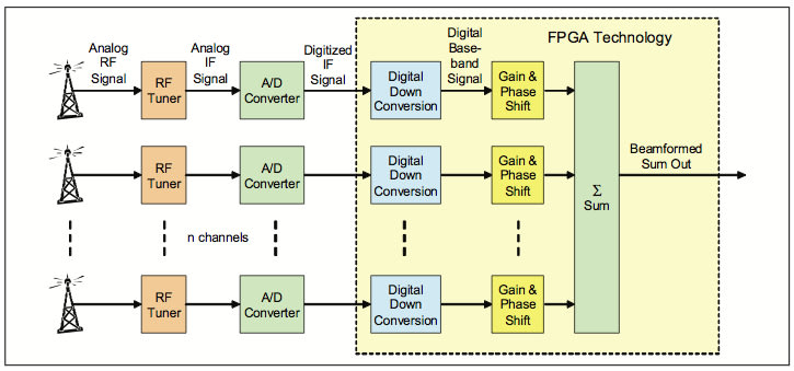
Figure 2 shows the basic signal processing tasks required for beamforming. The RF signals from the antenna must first be amplified and translated to an IF (intermediate frequency) signal to permit digitization by the A/D converter. Popular IF frequencies range from 21.4 to 160 MHz and many A/D converters now handle these signals with sampling rates between 80 and 500 Msamples/sec. These high-speed A/D converters connect directly to FPGAs with high speed LVDS interfaces supporting data converter peripherals operating at sample rates to 600 MHz and higher.
The next task is digital downconversion of the IF signal to baseband, producing a complex (I+Q) signal centered at DC or 0 Hz. In addition, the downconverted baseband signal is low-pass filtered to allow only the signal of interest to appear at the output. Together, these operations represent the classic software radio function — the DDC.
Inside the DDC, the frequency translation to baseband is performed by mixing the digital A/D input signal with digital samples from a numerically controlled local oscillator (NCO). The mixer employs two multipliers from the FPGA DSP blocks to handle the real A/D samples and the complex NCO samples.
The NCO is a phase accumulator (also part of the DSP block) followed by a sine look-up table. The table converts the steadily advancing phase value to sine wave samples. The NCO frequency is programmable by the operator to produce any frequency from DC to the A/D sample clock frequency. The complex baseband signal at the mixer output is fed into a low pass filter using DSP block multipliers, registers and adders. It features programmable filter coefficients to set the signal channel bandwidth.
Special circuitry incorporated in the NCO allows the user to offset the phase accumulator by a programmable angle to implement the phase shift requirement for beamforming. The gain adjustment is performed using a DSP block multiplier. Finally, the adjusted outputs of each DDC are summed together, again taking advantage of adders in the DSP blocks.
Beamforming Software Radio Module
A/D conversion plus all beamforming DSP operations for up to four channels can be handled in Pentek’s Model 71661 Software Radio Beamformer XMC module. As shown in Figure 3, it features four 200 MHz 16-bit A/D converters for digitizing the IF signals and a Virtex-6 LX240T FPGA for virtually all module functions, including the real-time beamforming software radio tasks.
Inside the FPGA are four digital downconverters (DDCs) which also incorporate the phase shift and gain adjustments. Each DDC can select from any of four A/D inputs to support different ratios of antennas to signal channels. Four power meters at each DDC output allow measurement of output power to help calibrate the gain settings for beamforming.
The Model 71661 also includes a summation block that adds the DDC outputs to form a four-channel beamforming sum. This block also accepts a propagated “sum in” signal from another module and generates a propagated “sum out” signal to the next module. The sum in and sum out signals use two X4 Aurora gigabit serial links connected through the P16 XMC connector, and each link is capable of moving data at 1.25 GB/sec peak. The final sum can be directed through the PCIe interface to the system CPU.
A clock and sync generator block accepts an external 5 or 10 MHz reference input to drive a phase-locked A/D sample clock synthesizer. A multi-pin LVPECL front panel connector supports synchronous sampling across multiple modules, which is an essential and critical requirement for all types of beamforming systems. The x4 or x8 PCIe interface operting at Gen 1 or Gen 2 speeds completes the link to the host processor, operating at peak transfer rates of up to 4 GB/sec.
Summary
Each new generation of FPGA opens up new classes of applications that were impractical with previous technology. The role of the FPGA in today’s software radio systems is so pervasive because it encompasses so many essential operations. As evidenced by the design of the 71661 module, virtually every device on the module connects to the FPGA.
For beamforming, FPGA functions include digital downconversion, synchronization and timing, phase and gain adjustments, power measurement, summation, gigabit serial links for summation propagation, the PCIe system interface for control, and high speed interfaces to A/Ds and other peripheral devices. As FPGA devices evolve, each of the key resources supporting these critical operations will be enhanced in performance and numbers, dictated by the importance of each to mainstream applications like software radio beamforming.
This article was written by Rodger Hosking, Vice President, Pentek, Inc., Upper Saddle River, NJ. For more information, Click Here
More From SAE Media Group
Automotive Engineering
Homing in on STEM Innovation
Aerospace & Defense Tech Briefs
Tackling Ruggedization Challenges for RF Communications in Software Defined Radios
Aerospace & Defense Tech Briefs
New RF Strategies for Software Radio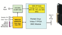
Aerospace & Defense Tech Briefs
Optimizing DSP Techniques for Antenna Site Software Radio
Aerospace & Defense Tech Briefs
What Today’s Advances in Radar Technology Mean for Testing and Training
Aerospace & Defense Tech Briefs
New Pulse Analysis Techniques for Radar and EW
Aerospace & Defense Tech Briefs
Software-Defined Analog Filters: A Paradigm Shift in Radio Filter Performance and Capability
RF & Microwave Technology
An Improved SDR FPGA Verification Methodology for Emerging OFDMA Waveforms
Aerospace & Defense Tech Briefs
Revolutionizing Electronic Warfare: Unleashing the Power of High-Performance Software-Defined Radios
Aerospace & Defense Tech Briefs
An Integrated Framework for Complex Radar System Design
Aerospace & Defense Tech Briefs
Advances and Challenges in Developing Radar Applications
Aerospace & Defense Tech Briefs
EW: New Challenges, Technologies, and Requirements
RF & Microwave Technology
Wireless Sensor Network with Geolocation
Aerospace & Defense Tech Briefs
Hardware Design of a High Dynamic Range Radio Frequency (RF) Harmonic Measurement System
Aerospace & Defense Tech Briefs
Enhancing Mission Readiness with Rugged Portable Instruments
Photonics & Imaging Technology
Understanding the New Optical Data Interface
Aerospace & Defense Tech Briefs
Validation of Ubiquitous 2D Radar
Tech Briefs
New Phase Shifter to Reduce Antenna Signal Loss
Aerospace & Defense Tech Briefs
Benefits and Challenges of Direct-RF Sampling for Avionic Platforms
Aerospace & Defense Tech Briefs
Explosive Ordnance Disposal (EOD) Jamming Unit
RF & Microwave Technology
The Basics of Multiple Input Multiple Output (MIMO) Radio Systems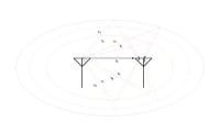
Aerospace & Defense Tech Briefs
Persistent Systems Auto-Tracking Antenna Adds Aircraft to Network, Enhances Data Sharing
Aerospace & Defense Tech Briefs
Making Fully Digital Beamforming for Radar and Electronic Warfare Applications a Reality
Aerospace & Defense Tech Briefs
Spectrum Processing Subsystems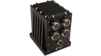
Aerospace & Defense Tech Briefs
Development of a 94 GHz Radar System for Dedicated Bird Detection at Airports and Airfields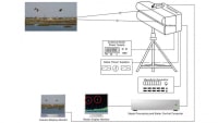
Aerospace & Defense Tech Briefs
The Inside Story on Unmanned Vehicle Signal Recorder Technology
RF & Microwave Technology
Jamming-Resistant Adaptive Radio System
Aerospace & Defense Tech Briefs
Improving Transmit/Receive Module Test Accuracy and Throughput
Aerospace & Defense Tech Briefs
Stepped-Frequency Distributed Radar for Through-the-Wall Sensing
Top Stories
INSIDERDefense
![]() New Raytheon and Lockheed Martin Agreements Expand Missile Defense Production
New Raytheon and Lockheed Martin Agreements Expand Missile Defense Production
NewsAutomotive
![]() Ford Announces 48-Volt Architecture for Future Electric Truck
Ford Announces 48-Volt Architecture for Future Electric Truck
INSIDERManufacturing & Prototyping
![]() Active Strake System Cuts Cruise Drag, Boosts Flight Efficiency
Active Strake System Cuts Cruise Drag, Boosts Flight Efficiency
ArticlesTransportation
![]() Accelerating Down the Road to Autonomy
Accelerating Down the Road to Autonomy
INSIDERMaterials
![]() How Airbus is Using w-DED to 3D Print Larger Titanium Airplane Parts
How Airbus is Using w-DED to 3D Print Larger Titanium Airplane Parts
Road ReadyTransportation
Webcasts
Electronics & Computers
![]() Cooling a New Generation of Aerospace and Defense Embedded...
Cooling a New Generation of Aerospace and Defense Embedded...
Power
![]() Battery Abuse Testing: Pushing to Failure
Battery Abuse Testing: Pushing to Failure
Connectivity
![]() A FREE Two-Day Event Dedicated to Connected Mobility
A FREE Two-Day Event Dedicated to Connected Mobility
Automotive
![]() Quiet, Please: NVH Improvement Opportunities in the Early Design Cycle
Quiet, Please: NVH Improvement Opportunities in the Early Design Cycle
Transportation
![]() Advantages of Smart Power Distribution Unit Design for Automotive &...
Advantages of Smart Power Distribution Unit Design for Automotive &...
Aerospace
![]() Sesame Solar's Nanogrid Tech Promises Major Gains in Drone Endurance
Sesame Solar's Nanogrid Tech Promises Major Gains in Drone Endurance