Making the Rounds in Aerospace: Tooling and Techniques for Discs, Blisks and Rings

Aerospace engine components like discs, blisks and rings are engineered to perform in extreme operating environments. They need to withstand intense heat and stress and be as lightweight as possible to meet exacting specifications.
These parts are also notoriously difficult to machine, and manufacturers who work with them must meet serious challenges of their own. Holding tight tolerances, maintaining predictable tool life and accounting for internal material stress relief from material removal can be especially difficult when profiling complicated features such as thin-walled flanges, undercut pockets and seal fins.
The challenges are also evolving. Advances in material science are leading to new exotic materials that are stronger, more heat-resistant and, as a result, even more difficult to machine. Meanwhile, machinists are asked to do more than ever while navigating ever increasing complexities in parts, machines and processes.
In this environment, the biggest challenge shops face is to become complacent — using the same tools and techniques they’ve been using for decades. Keeping pace with change isn’t easy, but taking advantage of the latest solutions can lead to greatly increased productivity, process security and quality when making these complex components. Here, we’ll look at some ways shops can overcome common challenges with the latest tools and techniques.
Part Conformity: Maintaining Precision When the Material Wants to Move

Machining discs, blisks and rings for aircraft engines takes exceptional precision, because any flaw or deviation can affect the engine’s performance. These parts may need to be machined to tolerances within one-thousandths of an inch or more. Adding to the challenge, internal stresses in the material may be released after unlocking the workpiece from the machining fixture, causing the component to flex or “spring back.”
Accounting for these stress releases is crucial to maintaining precise operations and hold tolerances for blisks, discs and rings, especially when removing material for thin-walled features. Understanding how metal removal and the order of operations affect stress relief in the component is essential.
To address this, it’s best to “sneak up” on the material with multiple roughing operations and setups. If there is any deformation, you still have enough material to bring it back into size. When roughing for a thin-walled feature, consider leaving extra material on the component, then do a semi-finish cut with a smaller cutting tool nose radius and less tool pressure. After that, remove the part from the fixturing to release any built-up stresses and flip it to rough the other side. This back-and-forth process may need to be repeated several times before finishing. It takes more time, requires more setups and may seem counterintuitive, but it’s the most effective way to accurately machine these parts to spec.
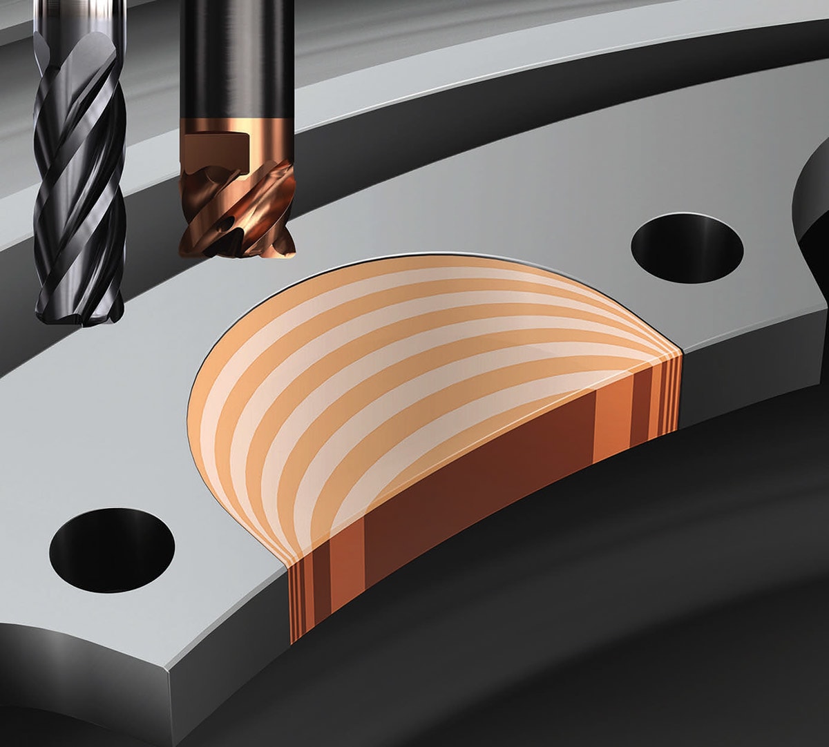
When milling out pockets for blisk blades, shops need to contend with an extreme blade wall thickness-to-length ratio that makes machining even more of an issue — not just for the immediate pocket being milled but also the adjacent pocket. Here, the order of operations is particularly important. One effective strategy is to skip over every other pocket all the way around the blisk and then continue to whittle down pockets around the component in a way that evenly distributes forces. Another option is to mill each blade pocket in a “pyramid like” technique by rough milling down toward the hub, leaving less material behind at the blade tip. Continue this technique for subsequent semi-finishing and finishing milling operations. This will give the blade more rigidity while being milled to size.
Choosing the Right Tools and Techniques to Drive Greater Efficiency

Machining nickel-based heat-resistant superalloys (HRSAs) and titanium to tight tolerances takes specialized tooling and machining techniques. These materials put heat back into the cutting tool, which can lead to greater wear, notching and increased risk of failures. Choosing tools, inserts and geometries that are optimized for heat-resistant materials and aerospace operations is critical to efficient production.
The right cutting tool and tool path technique can also benefit complicated turned features. For example, when turning pockets in blisks, discs and rings, shops can use specialized bladed round-insert cutters with trochoidal and scoop turning methods to remove material in hard-to-reach areas much more efficiently vs. traditional turning methods.
Trochoidal turning uses a back-and-forth zigzag motion that keeps the tool engaged with the material the entire time, minimizing engage/retract stress shocks to the insert and maximizing tool life. Scoop turning is better suited for deeper pockets and uses a similar pattern but only cuts in one direction on the down cut and then disengages from the material on the way out.
Choosing insert grades and geometries dedicated for specific applications can also make a big difference in production. When machining discs, for example, consider using a dedicated geometry when removing the forging skin. Forging skins can have a very different hardness and abrasiveness than the material underneath, which can lead to much worse performance, notching and tool wear.
When working on the disc itself, shops can further improve notch resistance, tool life and efficiency by using round inserts. These offer the lead angle, dual-sided contact and notch resistance needed for a dynamic turning CAM technique, which eases the tool into cutting and out again, back and forth, while the software dynamically adjusts the toolpath arc of engagement and feed rate. The feed rate is adjusted by calculating the chip thickness for a given arc of engagement. This takes advantage of the chip-thinning effect to increase inches per revolution when turning to boost productivity.
In finish turning operations, using inserts with cubic boron nitride (CBN) or polycrystalline diamond (PCD) coatings can dramatically improve productivity. CBN inserts are typically for hard part materials, but they can also be used on nickel alloy components to effectively maintain surface integrity and tolerance. They can also cut much faster than carbide, up to two or three times the surface speed. PCD inserts are ideal for titanium components like blisks or rings. They enable much faster cutting action, but because they can cut so aggressively, it’s critical to also use high-pressure coolant with these inserts.
Boosting Process Security With Better Technology

Few materials are harder on tools than titanium and HRSAs. To get the most out of your tooling and maintain optimal process security, there is a range of solutions and technologies available to manage heat, improve tool life and boost overall productivity.
When you’re dealing with titanium or HRSA components like discs, blisks and rings, it’s critical to use precise high-pressure coolant (at least 1,000 psi) to reach the high-heat area of the cutting zone. That means incorporating tools with precision coolant nozzles that deliver coolant to the tip of the tool. With the amount of heat generated from machining HRSAs, coolant sprayed or flooded from traditional nozzles can have difficulty cooling the cutting zone.
High-pressure coolant not only helps remove the heat; it also improves the metal chip control. It is difficult to break the chips with HRSA components, and this often results in long, nesting chips and stringers. Using high-pressure coolant helps to break those chips and keeps cutting operations running smoothly.
Tool holder solutions also have a critical role to play in process security. For example, turning long-reach pockets on a disc can apply a lot of cutting forces on the blade. A secure insert rail seat design with a screw-style holder assembly will make it far less susceptible to those forces that wear on the tool.

A rigid, modular setup for tool holding can provide benefits beyond security, such as faster tool changeouts, dampened antivibration options and high-pressure coolant capabilities. Some solutions available today can offer a wide range of high-pressure coolant options such as multiple over/under coolant channels for precise coolant spray control.
Shops can also take advantage of new sensor-equipped turning adaptors and driven tool holders to improve predictive maintenance and data-driven efficiency. These smart tool holders can gather and transmit data via Bluetooth to a computer or tablet, letting operators monitor temperature, vibration and rpm in real time to optimize cutting speeds and make proactive maintenance decisions.
Data from these solutions can also tie into a plantwide system for overall production efficiency. Some tool providers offer advanced data analytics software that can aggregate and analyze machine data to provide actionable insights. This type of software can be used by everyone, from operators to production managers, to optimize manufacturing processes, increase machine utilization and improve profitability.
Finding the most efficient way to machine the complicated features in discs, blisks and rings can require some trial and error, know-how and expertise. But it’s important to remember that shops aren’t on their own. Some tool providers are able to offer more comprehensive engineering services and support, beyond just cutting tools. The right provider should be able to deliver holistic guidance in everything from optimized tooling processes and CAM software to application engineering and machining trials.
Working with global suppliers that are committed to aerospace manufacturing will also give you access to the support and service you need to machine components more productively from start to finish. Whether you’re working with discs, blisks or rings, they’ll have the experience and solutions to help you achieve optimal production outcomes throughout your operation.
This article was written by Tom Funke, CAM and Applications Specialist - Aerospace, Space and Defense, Sandvik Coromant (Melbane, NC). For more information, visit here .
Top Stories
INSIDERRF & Microwave Electronics
![]() FAA to Replace Aging Network of Ground-Based Radars
FAA to Replace Aging Network of Ground-Based Radars
PodcastsDefense
![]() A New Additive Manufacturing Accelerator for the U.S. Navy in Guam
A New Additive Manufacturing Accelerator for the U.S. Navy in Guam
NewsSoftware
![]() Rewriting the Engineer’s Playbook: What OEMs Must Do to Spin the AI Flywheel
Rewriting the Engineer’s Playbook: What OEMs Must Do to Spin the AI Flywheel
Road ReadyPower
![]() 2026 Toyota RAV4 Review: All Hybrid, All the Time
2026 Toyota RAV4 Review: All Hybrid, All the Time
INSIDERDefense
![]() F-22 Pilot Controls Drone With Tablet
F-22 Pilot Controls Drone With Tablet
INSIDERRF & Microwave Electronics
![]() L3Harris Starts Low Rate Production Of New F-16 Viper Shield
L3Harris Starts Low Rate Production Of New F-16 Viper Shield
Webcasts
Energy
![]() Hydrogen Engines Are Heating Up for Heavy Duty
Hydrogen Engines Are Heating Up for Heavy Duty
Energy
![]() SAE Automotive Podcast: Solid-State Batteries
SAE Automotive Podcast: Solid-State Batteries
Power
![]() SAE Automotive Engineering Podcast: Additive Manufacturing
SAE Automotive Engineering Podcast: Additive Manufacturing
Aerospace
![]() A New Approach to Manufacturing Machine Connectivity for the Air Force
A New Approach to Manufacturing Machine Connectivity for the Air Force
Software
![]() Optimizing Production Processes with the Virtual Twin
Optimizing Production Processes with the Virtual Twin
