


High-Flying Output: Key Machining Techniques for Structural Aircraft Components
Structural aircraft components and the methods for making them have changed significantly, driven by advancements in technology and new demands in the industry. Aerospace assemblies are becoming lighter and more complex, while every aspect of how these components are designed and made is evolving.
As CAD and finite element analysis (FEA) allow engineers to optimize every surface for strength and weight, structural components are taking on more sophisticated forms. Many parts today are delivered at near-net shape, which can reduce waste and roughing operations, but on the other hand, can present more challenging features to machine.

Some components that may have once required separate pieces and fasteners are now designed as a single, consolidated part. Other parts are trading bulky features for latticework, thinner walls and sweeping curves to minimize material and reduce weight. These intricate features can challenge even the most experienced machinists.
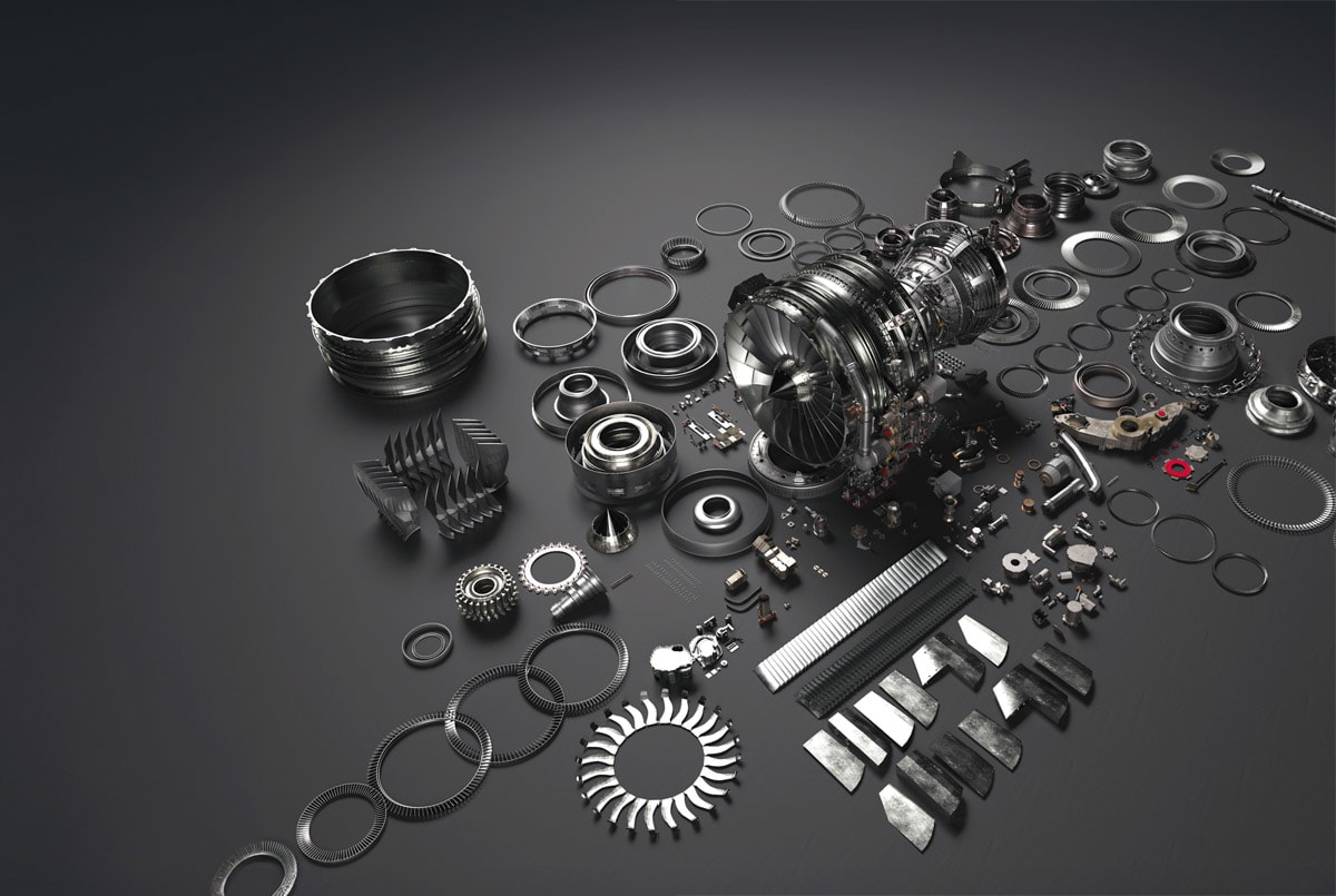
The best strategies for tackling your machining challenges depend on the type of structural component. In this article, we’ll examine two categories: airframe components, such as fuselage panels, wing spars and bulkheads, and engine-side structural components like engine mounts or casings.
For airframe components, weight is extremely important, so they’re often formed with lighter materials like aluminum or magnesium. On the engine side, components must withstand extreme temperatures generated from the engine, making heat-resistant metals like titanium and nickel-based alloys the preferred materials.
Each type of material and structural component comes with its own unique challenges, but with the right cutting tools and the right techniques, aerospace manufacturers can improve the quality and efficiency of their machining processes to enhance their overall production.
Need for Speed and Chip Control

The wing, fuselage and bulkhead components that give an aircraft its essential shape and structural integrity need to be lightweight, strong and machined to close tolerances. These tolerances may be more forgiving than engine components, but working with the massive size of wing ribs or frames introduces a level of complexity that can make it difficult to meet precise specifications.
The materials favored for airframes include a wide range of aluminum and magnesium alloys, often with added silicon content for strength. These metals are chosen for their combination of machinability, durability and, most importantly, their light weight. The low density of aluminum and magnesium make them easier to work with, so the main challenge here isn’t cutting the material — it’s more about removing serious volumes of metal quickly without gumming up cutting tools with chips.
High spindle speeds and accelerated machining feeds are the key. That means using machines designed to handle the aggressive cutting and tooling needed for high-speed aluminum cutting. The optimal tools for aluminum often have uncoated grades, sharp geometry edges on the inserts and fewer flutes that are wide and open. Having fewer flutes may seem counterintuitive, but, with softer metals, the wider flutes can take deeper cuts and help to clear the chips. However, aluminum alloys that include higher silicon content are more abrasive on cutting tools and might require tougher solutions like polycrystalline diamond-coated (PCD) inserts.
Avoiding chip buildup around the cutting tool is critical to maintaining efficient operations. Shops may use a variety of methods for chip control, ranging from high-pressure coolant to dry cutting with air guns to clear the chips. Using horizontal machines also helps for applications like latticework on a wing component. Gravity can work in your favor, letting chips fall away quickly so you’re not recutting chips.
Techniques to Tackle Challenging Airframe Features
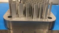
When it comes to features on airframe parts, thin-walled elements like lattice structures are a common machining challenge. When pocketing to produce thin walls, it’s easy for these parts to succumb to vibration, flex or chatter, which can wear down cutting tools or worse — compromise the integrity of the part. To overcome this, machinists can use a waterline, or “Christmas tree,” technique, staggering the machine cuts along the way to maintain the profile tolerance. This technique lets machinists maintain a more stable length-to-width ratio on the wall and gradually remove material with less risk of deformation, leaving staggered steps in the cut that resemble a Christmas tree.
Elaborate curves are another common challenge in airframe parts. Aerodynamic designs often require contoured or 3D shapes that can test both machine capability and tool path programming skills. For machining these forms, turn milling with an indexable or solid carbide bullnosed cutter on a 5-axis or 4-axis horizontal machine can work well. Or, on other shapes, you may need to use barrel-nose cutting tools and Sidewall Axial Relief Feed (SWARF) cuts to achieve the desired results. Effective cutting strategies and careful cutting tool selection are critical to developing consistent, repeatable processes that minimize cost per part.
Engine mounts and casings introduce another level of complexity for machinists. These parts encounter extreme conditions and require tough materials like titanium, Inconel and other nickel-based superalloys that can withstand extreme heat and stress. While these components may not match the large scale of airframe structures, the cost and risk factor are amplified. Mistakes can become costly very quickly, both in terms of scrapped material cost and machine downtime.
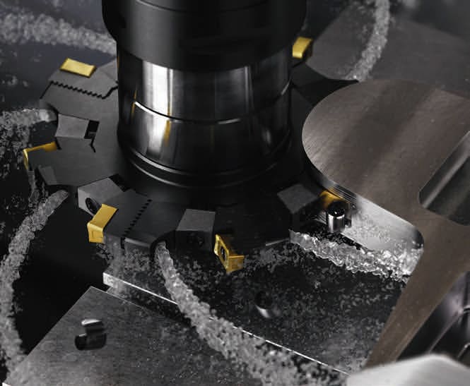
Tooling is critical here to achieve secure, repeatable processes at the lowest cost per unit. Diamond-coated inserts, for example, work well for finishing titanium parts with turning operations. Nickel alloys, on the other hand, may respond well to ceramic tools for roughing operations, allowing for rapid, cost-effective metal removal. For both materials, carbide tooling optimized for aerospace combined with high-pressure coolant is the workhorse, striking an optimal balance between productive metal cutting and tool longevity.
Enhancing Efficiency on Engine-Side Features
Machining strategies for engine-side work must address both the difficulty of the material and the intricacy of the features. Features like deep pockets for engine mounts can test the limits of cutting tool reach and stability, especially with difficult materials like titanium. For example, if a cutting tool extends more than four times its diameter deep into a cut, vibration can become a serious issue. Using heavy-duty hydraulic holders or dampened holders, along with dampened cutting tools, can help minimize those vibrations, stabilize processes and hold tolerances.
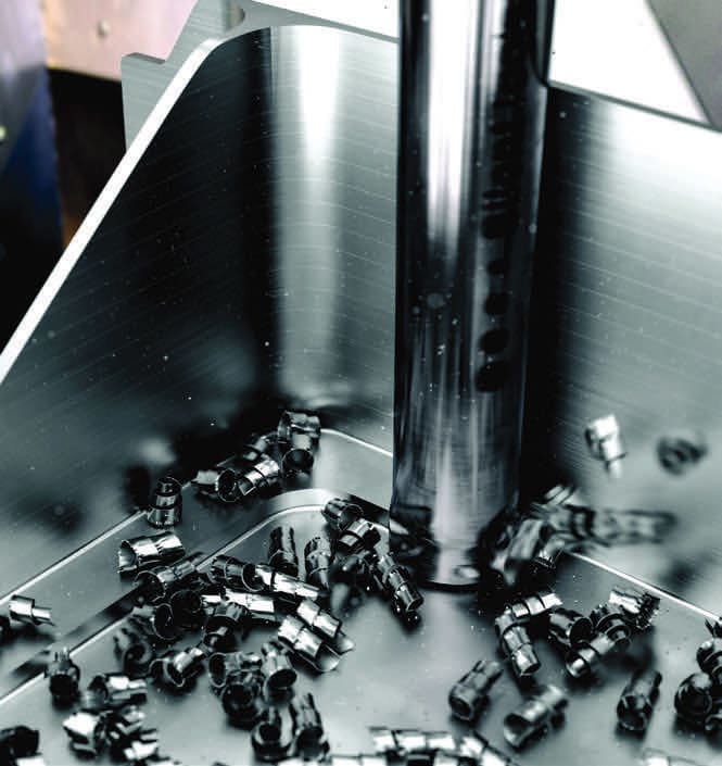
There are several useful techniques to securely machine deep pockets. Using approaches like continuous ramping, similar to “helical interpolation,” can be effective to minimize vibrations or sudden deflections, improve tool life and hold tolerances. This method keeps the tool continuously engaged with the material by following along the path of the pocket, slowly removing more material on each pass for a more stable process and consistent surface finish. Dynamic milling is another effective technique that leverages a long-edge cutter and optimized tool cutting paths to manage chip load and heat distribution. This approach takes advantage of the high-feed chip-thinning effect of a long-edge cutter by using a large axial depth of cut and relatively small radial depths of cut.
Elaborate shapes and close tolerance profile requirements are also a common challenge with engine-side work. These complicated surfaces often require point milling techniques with ball-nose end mills, a process that can be painstakingly slow in hard alloys. Efficient approaches require creative planning, sometimes leveraging specialized cutting tool geometries, 5-axis machining strategies and highly optimized tool cutting paths with advanced software.

Digital simulation software can help take tool cutting path planning to the next level and reduce machining time on these complex features. NC code simulation software, such as Vericut, can analyze CAM programs to evaluate cutting forces, tool engagement and material, and then adjust machine feed rates to optimize cutting data at every point in the process.
Tackling the evolving challenges of structural components for aircraft while focusing on efficient, profitable operations requires a mindset geared toward continuous improvement and an eye for the bigger picture. Improving productivity isn’t just about the right tools or techniques — it requires looking at every aspect of production, from the coolant and toolholders to the machines and software.
This article was written by Tom Funke, Aerospace Technical Leader, Sandvik Coromant (Mebane, NC). For more information, visit here .
More From SAE Media Group
Aerospace & Defense Tech Briefs
Manufacturing Spotlight: Advanced Drilling, Threading and Milling Tools Maximize Productivity in Challenging Aerospace Materials
Aerospace & Defense Tech Briefs
Making the Rounds in Aerospace: Tooling and Techniques for Discs, Blisks and Rings
Aerospace & Defense Tech Briefs
Aerospace Production: Overcoming Challenges in Composite Machining
Aerospace Manufacturing and Machining
Machining Titanium Aero-Frames
Medical Design Briefs
A Versatile Tool for CNC Machining of Medical Devices
Aerospace & Defense Tech Briefs
Finding the Perfect Aluminum for Additive Manufacturing
Aerospace Manufacturing and Machining
Why Heat Exchanger Manufacturers Need to Rethink Design and Fabrication
Medical Design Briefs
Product Focus: Manufacturing/Assembly Equipment
Aerospace Manufacturing and Machining
Tips for Choosing CBN Grinding Wheels


NASA Spinoff
Rocket Manufacturing Meets Science Friction
Aerospace & Defense Tech Briefs
Optimized Cutting Tools for Tomorrow’s Sustainable Aircraft
Aerospace & Defense Tech Briefs
Why the Turbomachinery Industry is Increasingly Bullish on Additive Manufacturing
Aerospace & Defense Tech Briefs
5-Axis Machining Center
Aerospace & Defense Tech Briefs
Reducing the High Cost Of Titanium

Aerospace Manufacturing and Machining INSIDER
Riveting Technology Enables Lightweight Magnesium Fasteners for Fuel Efficiency
Aerospace & Defense Tech Briefs
New Products

Aerospace & Defense Tech Briefs
Pulse Plasma Nitriding for Aerospace Applications
Aerospace Manufacturing and Machining INSIDER
How Airbus is Using w-DED to 3D Print Larger Titanium Airplane Parts

Aerospace & Defense Tech Briefs
Aerospace Manufacturers Turn to Non-Hazardous PVD Coatings as Regulations Tighten on Toxic Hard Chrome Plating
Aerospace Manufacturing and Machining
CAM Software Technology Keeps Pace with Aerospace Manufacturing Challenges


Top Stories
INSIDERManufacturing & Prototyping
![]() How Airbus is Using w-DED to 3D Print Larger Titanium Airplane Parts
How Airbus is Using w-DED to 3D Print Larger Titanium Airplane Parts
INSIDERManned Systems
![]() FAA to Replace Aging Network of Ground-Based Radars
FAA to Replace Aging Network of Ground-Based Radars
NewsTransportation
![]() CES 2026: Bosch is Ready to Bring AI to Your (Likely ICE-powered) Vehicle
CES 2026: Bosch is Ready to Bring AI to Your (Likely ICE-powered) Vehicle
NewsSoftware
![]() Accelerating Down the Road to Autonomy
Accelerating Down the Road to Autonomy
EditorialDesign
![]() DarkSky One Wants to Make the World a Darker Place
DarkSky One Wants to Make the World a Darker Place
INSIDERMaterials
![]() Can This Self-Healing Composite Make Airplane and Spacecraft Components Last...
Can This Self-Healing Composite Make Airplane and Spacecraft Components Last...
Webcasts
Defense
![]() How Sift's Unified Observability Platform Accelerates Drone Innovation
How Sift's Unified Observability Platform Accelerates Drone Innovation
Automotive
![]() E/E Architecture Redefined: Building Smarter, Safer, and Scalable...
E/E Architecture Redefined: Building Smarter, Safer, and Scalable...
Power
![]() Hydrogen Engines Are Heating Up for Heavy Duty
Hydrogen Engines Are Heating Up for Heavy Duty
Electronics & Computers
![]() Advantages of Smart Power Distribution Unit Design for Automotive...
Advantages of Smart Power Distribution Unit Design for Automotive...
Unmanned Systems
![]() Quiet, Please: NVH Improvement Opportunities in the Early Design...
Quiet, Please: NVH Improvement Opportunities in the Early Design...