


Reduced Power Laser Designation Systems
The system would locate, identify, range, and mark stationary and moving targets.
This work contributes to the Micropulse Laser Designation (MPLD) project to develop a six-pound eye-safe micro-pulse laser system to locate, identify, range, mark, and designate stationary and moving targets. MPLD uses laser pulses of much lower energy and higher repetition rates than in existing laser designation systems. Because of this, MPLD presents a range of new circuit design and signal processing problems.
Work to date has involved investigating techniques for increasing photodiode amplifier bandwidth and reducing photodiode amplifier noise. A basic calculation of visibility angles for urban environments has also been made. A photodiode can be modeled as a current source in parallel with a capacitance. The photodiode envisaged for the present system has capacitance CD = 225 pF. The consideration is to minimize the noise of the circuit; unfortunately, photodiode amplifiers have very complex noise response.
The appropriate amplifier for a photodiode is a current-to-voltage amplifier (transconductance amplifier). Because of the virtual ground at the op-amp's inverting input pin, the voltage across the diode is very small. This helps to ensure a large amplifier bandwidth by reducing currents through the diode capacitance CD, thereby ensuring that almost all of the diode current passes through the feedback resistor rather than through CD. Bandwidth can be further increased by decreasing the closed-loop gain of the op-amp connected to the diode. If this is done, the overall gain can be brought up to the desired value by using more than one stage of amplification.
When used as a photodiode amplifier, the transconductance amplifier exhibits a complex noise behavior, in spite of the apparent simplicity of the basic circuit. The noise behavior of the photodiode amplifier has the following two undesirable properties that distinguish it from most other op-amp circuits:
- There is "noise gain peaking" at high frequencies due to the interaction of parasitic capacitances within the amplifier. Above a certain frequency, the noise gain increases before eventually leveling off and then decreasing again once the op-amp's open-loop gain roll-off is reached.
- The circuit amplifies the signal with a lower bandwidth than that with which the noise is amplified.
This project is investigating several approaches to increasing the signal bandwidth of the amplifier, and limiting the adverse effects of noise caused by noise gain peaking and excessive noise-gain bandwidth.
This work was done by Barry G. Sherlock of the University of North Carolina at Charlotte for the Naval Surface Warfare Center.
NSWC-0001
More From SAE Media Group
Tech Briefs
Hybrid, Wide-Range Detector Amplifier
Aerospace & Defense Tech Briefs
Analysis of Analog Photonic Links Employing Multiple-Channel (Arrayed) Receivers
Aerospace & Defense Tech Briefs
Effect of Laser Noise on an Analog RF/Photonic Link
Aerospace & Defense Tech Briefs
Photonic Recirculating Delay Line for Analog-to-Digital Conversion
Photonics Tech Briefs
Automatic Alignment of Displacement-Measuring Interferometer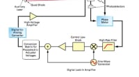
Photonics Tech Briefs
Leakage-Compensated, Frame-Differencing APS Imager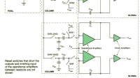
Aerospace & Defense Tech Briefs
Stimulated Brillouin Scattering (SBS) Suppression and Long Delivery Fibers at the Multikilowatt Level with Chirped Seed Lasers
Photonics & Imaging Technology
Photonics-Based Wireless Link Breaks Speed Records for Data Transmission
Tech Briefs
Sensitive Optical Receivers for Space
Photonics Tech Briefs
Stabilizing Microwave Frequency of a Photonic Oscillator
Aerospace & Defense Tech Briefs
Photonic Analog-to-Digital Converters
Aerospace & Defense Tech Briefs
Apparatus Generates CE-Phase-Stable Two-Cycle Optical Pulses
Photonics Tech Briefs
A High-Repetition-Rate Optical Communications Source
Tech Briefs
Fast-Tunable Laser System
Aerospace & Defense Tech Briefs
Compact Megawatt Infrared Free-Electron Laser Amplifier
Aerospace & Defense Tech Briefs
High-Power Broadband Multispectral Source on a Hybrid Silicon Chip
Photonics Tech Briefs
80-GHz MMIC HEMT Voltage-Controlled Oscillator
Photonics & Imaging Technology
Creating High-Precision Glass for NIR Lasers
Photonics & Imaging Technology
Optical Signal Amplifying Technique
Tech Briefs
Free-Space Fiber Optic Laser Rod
Tech Briefs
Coherent Optical Transistor
Aerospace & Defense Tech Briefs
Heterodyne RF/Optical Links Utilizing Integrated Photonics
Photonics Tech Briefs
Opto-Electronic Oscillator Using Suppressed Phase Modulation
Photonics Tech Briefs
Fiber Laser Amplifiers with Broad Applications

Photonics Tech Briefs
Fiber-Optic Phase-Locked Loop Sensitive to Local Strain Only

Photonics Tech Briefs
OEOs With Carrier Suppression for Reduction of Phase Noise
Top Stories
INSIDERManufacturing & Prototyping
![]() How Airbus is Using w-DED to 3D Print Larger Titanium Airplane Parts
How Airbus is Using w-DED to 3D Print Larger Titanium Airplane Parts
NewsAutomotive
![]() Microvision Aquires Luminar, Plans Relationship Restoration, Multi-industry Push
Microvision Aquires Luminar, Plans Relationship Restoration, Multi-industry Push
INSIDERAerospace
![]() A Next Generation Helmet System for Navy Pilots
A Next Generation Helmet System for Navy Pilots
INSIDERDesign
![]() New Raytheon and Lockheed Martin Agreements Expand Missile Defense Production
New Raytheon and Lockheed Martin Agreements Expand Missile Defense Production
ArticlesAR/AI
![]() CES 2026: Bosch is Ready to Bring AI to Your (Likely ICE-powered) Vehicle
CES 2026: Bosch is Ready to Bring AI to Your (Likely ICE-powered) Vehicle
Road ReadyDesign
Webcasts
Semiconductors & ICs
![]() Advantages of Smart Power Distribution Unit Design for Automotive...
Advantages of Smart Power Distribution Unit Design for Automotive...
Unmanned Systems
![]() Quiet, Please: NVH Improvement Opportunities in the Early Design...
Quiet, Please: NVH Improvement Opportunities in the Early Design...
Electronics & Computers
![]() Cooling a New Generation of Aerospace and Defense Embedded...
Cooling a New Generation of Aerospace and Defense Embedded...
Power
![]() Battery Abuse Testing: Pushing to Failure
Battery Abuse Testing: Pushing to Failure
AR/AI
![]() A FREE Two-Day Event Dedicated to Connected Mobility
A FREE Two-Day Event Dedicated to Connected Mobility