


More sting for the STINGRAY
GM Propulsion engineers elevate the evergreen small-block V8 to new heights for its mid-engine Corvette mission.
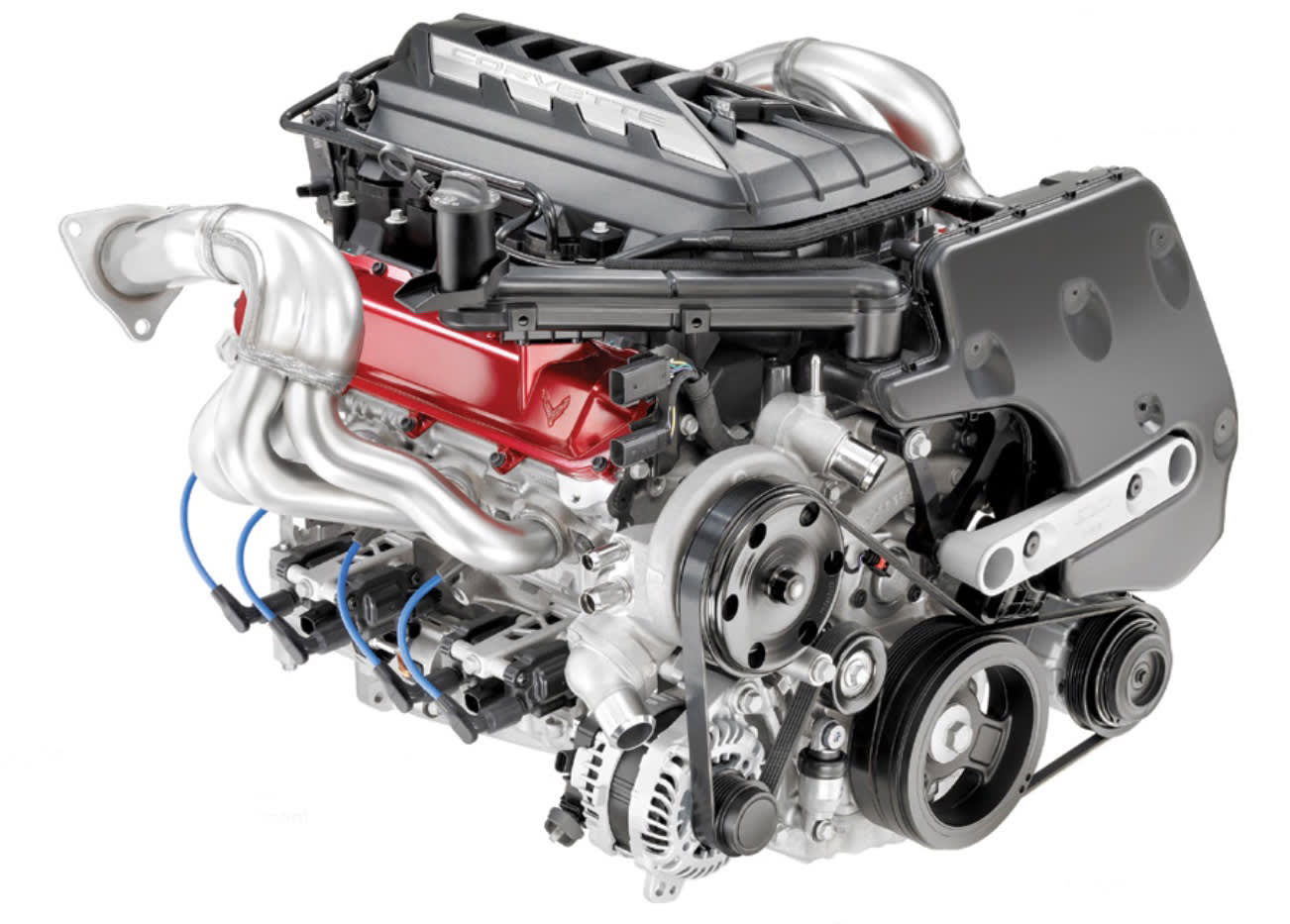
Instead of heaving decades of small-block V8 expertise out the window, GM Propulsion engineers led by chief engineer Jordan Lee leveraged past success to create a new-for-2020 V8. Known as the LT2, the 6.2-L V8 gives Chevy’s all-new, eighth-generation 2020 Corvette more power (the most yet in the base Stingray), stirring response, and competitive fuel efficiency compared with the outgoing C7.
And the small-block, with its single camshaft in block and two valves per cylinder, remains unmatched versus its rivals in three key metrics: bill of material, package efficiency, and the power-per-dollar quotient. It’s the payoff for 65 years of continuously refining (and never giving up on) a brilliant original design.
While the eighth-generation Corvette is revolutionary in scope, its LT2 ingeniously blends innovation with traditional design features.
Cylinder block
While it continues the small-block’s classic 4.40-inch (111.8-mm) bore spacing, the LT2 cylinder case is a fresh design with key features related to Corvette’s move to mid-engine architecture. To facilitate mounting the engine as low as possible in the chassis for optimum performance, dry sump lubrication is standard equipment.
Lubrication and ventilation systems are thoroughly revised to assure reliable oiling across the full operating range (6600 rpm redline). That includes flat-out driving conditions with ambient temperatures up to 100-deg.F, and while loaded to 1.2-g in all three directions.
To prevent oil from draining from the cylinder heads and valve lifters into the crankcase, the LT2’s valley compartment between the cylinder banks is sealed at its bottom. According to Lee, this arrangement (an all-time first, Automotive Engineering believes) greatly diminishes aeration of the lubricant by the crankshaft and windage losses caused by the crank whirling in a mist of oil droplets. A gerotor pump, driven by the camshaft via chain, scavenges oil from the valley, returning it to the 7.5-quart (7-L) injection-molded reservoir mounted to the left front corner of the engine.
The new deep skirt block is A319-T7 cast aluminum, as before, with cast-iron bore liners and cross-bolted nodular-iron main bearing caps to help secure the crankshaft. The block’s flanks feature new ribbing, engine mount bosses and attachment points for the eight ignition coils. The 4.065-in (103.25-mm) bore, 3.622-in (92.0-mm) stroke, and 9.24-in (234.7-mm) deck height are carried over from the LT1 V8.
Block bottom cover
The low-profile bottom ‘pan’ is a high-pressure aluminum die casting with 3.5-mm (0.13-in) wall thicknesses. Two distinct bays collect oil draining from piston-cooling jets and the crankshaft and cam bearings; each bay is scavenged by a crank-driven gerotor pump. A molded plastic scraper peels oil clinging to the crankshaft counter-weights. An external oil-to-coolant heat exchanger bolted to the side of the oil sump is rated at 23 kW, 28% greater cooling capacity than the LT1’s oil cooler. The oil filter mounting boss is integral with this component.
Lubrication and ventilation
The LT2’s 450-mm x 370-mm x 195-mm (17.7-in x 14.6- in x 7.7-in) plastic dry-sump oil tank, supplied by BASF, is 30% glass-filled PA66+PA6, known as Ultramid. It also handles centrifugal separation of the inbound oil and vapor. Attaching the reservoir directly to the engine trims mass, complexity, and flow losses inherent to external lines, Lee explained. A crank-driven vane pump provides low and high lubrication outputs to minimize parasitic losses below the 5,500-rpm switching point. Vent lines run from the reservoir to the cylinder-head covers which are in turn plumbed to the intake manifold so no oil vapor escapes to atmosphere.
In the LT1 V8, up to three quarts (2.8 L) of lubricating oil can be trapped in the engine during harsh operating circumstances, increasing the likelihood of momentary pressure pump starvation. In the LT2, less than one quart of the Dexos 2 0W40 synthetic oil is in use at redline. Lee claims this greatly enhances the new lubrication system’s reliability and facilitates a 2.2-quart reduction of the V8’s oil supply, compared with the LT1. That trims 3.7-lb (1.7- kg) of mass and reduces the cost of each oil change.
Crankshaft
A switch to S38 alloy steel improves the strength of the LT2’s forged crankshaft vs. the LT1. A longer nose extension drives the three stacked oil pumps. The front damper has an aluminum hub and steel inertial ring equipped with a ribbed outer surface to drive accessories via rubber belts. A second damper at the rear of the engine connects the crankshaft to the dual-clutch automatic transaxle. This device diminishes torsional vibration, a concern while switching to the LT2’s fuel-saving Active Fuel Management four-cylinder operating mode.
The rear damper is small in diameter because no flywheel or torque converter is required with the new automatic transmission. Extra effort was invested in locating the new transaxle’s input shaft below its output shafts to facilitate the lowest possible engine mounting and center of gravity.
Intake and exhaust systems
A key advantage with the mid-engine layout is more space and flexibility in the design of intake and exhaust systems. Chief engineer Lee acknowledges that there’s nearly three more inches (76-mm) of height available for a larger intake plenum—with its internal volume increased from 13.5- to 16.0 L and more efficient runners—because there’s no risk of the engine blocking the driver’s view of the road ahead. While the LT1 had six 225-mm-long runners and two 185-mm runners (due to space limitations), the new LT2 intake provides eight runners all of which are 210 mm in length.
The intake manifold consists of four ‘shells’ made of injection molded PA66. These pieces are welded together using a vibratory friction process that temporarily melts mating surfaces. The eight runners are 210 mm (8.27-in) long. The 87-mm (3.42-inch) throttle body, now aimed toward the rear of the car, is the same diameter as the LT1’s. Since the black plastic intake manifold isn’t particularly attractive, designers hid it beneath a molded plastic cover textured to coordinate with the Corvette’s rear body surfaces.
GM designers also collaborated with powertrain engineers to perfect the routing and surface finish of the LT2’s stainless-steel exhaust headers. The classic four-into-one layout has tubular runners, a brass-colored hue, and gently tapered collectors feeding a single-volume, close-coupled catalyst per side. Each cat is 132.1-mm in diameter x 140.0-mm long, yielding 1.9 L of internal volume. The ceramic bricks are drilled for O2 sensor clearance.
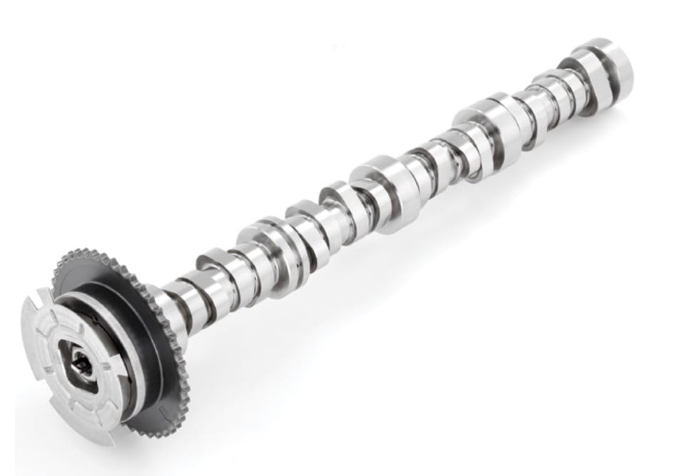
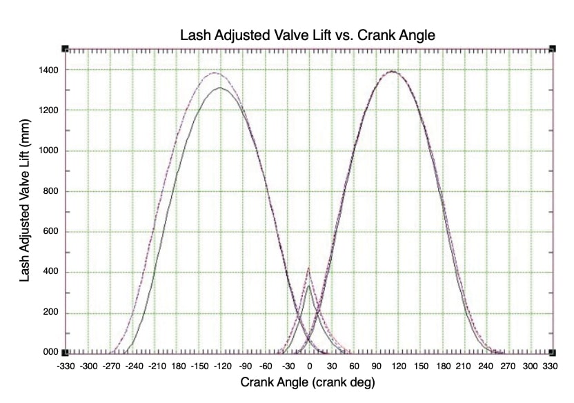
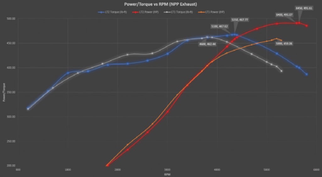
Lee’s engineering team took full advantage of the newfound volumetric efficiency with a more aggressive camshaft design. Exhaust valve lift was increased from 13.5-mm (0.53-in) to 14.0-mm (0.55-in) and duration was upped a significant 18-deg. over the LT1’s exhaust-valve timing. Intake duration was increased by 4-deg. While these changes sacrificed some power and torque in the mid-range (2800—4500 rpm), there are significant gains in both above 5000 rpm. Claimed peak torque of 465/470 lb-ft (637 N-m, with/without the optional performance exhaust system) is attained at 5150 rpm. The SAE J1349-certified 490/495 hp peak (365/369 kW; a 30/35 hp gain over the LT1) arrives at 6450 rpm.
The LT1’s variable valve timing system providing up to 62 degrees of cam phasing authority and GM’s AFM cylinder deactivation system both carry over in the interests of cruising serenity and fuel efficiency. Engine control is via GM’s 32-bit E99 ECU.
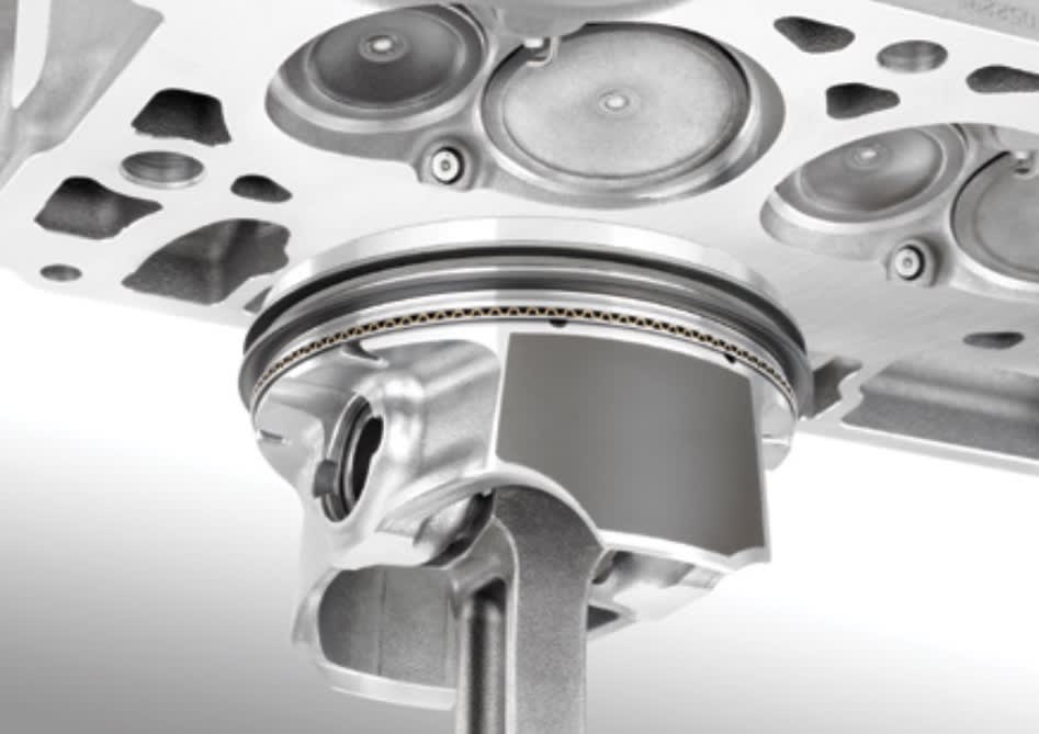
Cylinder heads
Cast in A319-T7, these components are largely unchanged from the LT1 designs. The 59-cc combustion chambers, valve sizes (2.13 in / 54 mm intake, 1.59 in / 40.4 mm for the sodium-filled exhaust), and 11.5:1 compression ratio carry over. Like the LT1, the new LT2 employs direct fuel injection, operating at 2,175 psi (15 Mpa) maximum pressure.
Engine testing
Proving the new Corvette’s speed and stamina required countless laps around the Milford (Michigan) Road Course, the Nurburgring’s grueling Nordschliefe, Virginia International Raceway, and the Papenburg (Germany) 12.3-km (7.6-mile) banked oval. Tilt-stand tests in GM Propulsion’s Pontiac technical center verified that the lubrication system was capable of maintaining pressure when subjected to a simulated 1.2 g in every direction. While several engine failures have been noted by owners (read competitive manufacturers) who submitted C7 Corvettes to racetrack lapping, Lee proudly reports that only a single notable ‘problem’ throughout the new Corvette’s comprehensive development program.
Manufacturing
The LT2 is manufactured at GM’s Tonawanda, NY, engine plant using contemporary CNC flexible machining centers in lieu of transfer lines. Built in 1937, Tonawanda has been the small-block V8’s home since its 1955 inception. While the plant established a world record building 8,832 engines in one day, current small-block production is 2,200 units/day. LT2 output for the new Corvette is slated at 170 engines/day.
More From SAE Media Group
Off-Highway Engineering
Navistar Updates A26 Engine, Improves FE by 4%
Automotive Engineering
GM details Corvette’s new and mighty LT6 V8
Automotive Engineering
Chevrolet Delivers a Bombshell with First-Ever 4-Cylinder for Fullsize Pickups
Automotive Engineering
Audi Evolves the Miller Cycle in Its New 2.0-L Spark-Ignition Engine
Automotive Engineering
Ferrari Massages 458 to Create 488 GTB
Automotive Engineering
Pushing the ICE Forward, Gradually
Automotive Engineering
Unique Helmholtz Induction Feeds 2023 Corvette Z06
Off-Highway Engineering
Cummins Mid-bore X10 Engine Raises the Performance Bar
Off-Highway Engineering
Cummins Has a V8 for Commercial Applications
Automotive Engineering
Lithium-Free Corvette Z06: More Sting for the 2023 Stingray
Automotive Engineering
First Look: GM’s New Modular Ecotec Engines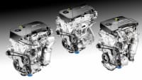
Automotive Engineering
German Spark-Ignited Compression-Ignition Research Paralleling Mazda’s SPCCI
Automotive Engineering
New Chevy Corvette ZR1’s LT5 V8: 2 Hp per Cubic Inch
Automotive Engineering
New Peugeot 3-Cylinder Gasoline Engine Family Optimizes Combustion
Automotive Engineering
Achates Powers toward Production
Off-Highway Engineering
MAN Launches Heavy-Duty Truck Diesel Engine
Automotive Engineering
New Axial-Piston Engine Aimed at Range Extenders, Military Applications
Off-Highway Engineering
Mahle, Liebherr Develop Active Pre-Chamber for Hydrogen ICE
Automotive Engineering
2022 Nissan Rogue Gets a VC Turbo Triple
Automotive Engineering
Mercedes-AMG Extracts World-Record Power from New Four-Cylinder Engine
Automotive Engineering
Optimizing Hybrids for Cost and Efficiency
Automotive Engineering
An Exhaust Symphony in the Key of C8
Automotive Engineering
Continental Debuts First Production Aluminum Turbocharger Housing
Automotive Engineering
SwRI’s D-EGR Demo Car Wows SAE Engines Symposium with 42% BTE
Automotive Engineering
Frictionless Engine Seals
Automotive Engineering
V-Charging Aims to Add Muscle to Downsized Engines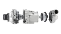
Automotive Engineering
New-Gen Torque Converter Aims at 2017 Vehicle Intro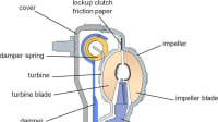
Automotive Engineering
Extending a Wankel Future on Hydrogen Fuel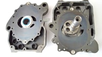
Automotive Engineering
2016 Pentastar V6 Adds New VVT, Cooled EGR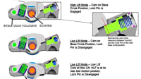
Automotive Engineering
New Four-Chamber Rotary Engine Could Supplant Wankel and Piston Engines for UAV Applications
Top Stories
NewsSensors/Data Acquisition
![]() Microvision Aquires Luminar, Plans Relationship Restoration, Multi-industry Push
Microvision Aquires Luminar, Plans Relationship Restoration, Multi-industry Push
INSIDERRF & Microwave Electronics
![]() A Next Generation Helmet System for Navy Pilots
A Next Generation Helmet System for Navy Pilots
INSIDERWeapons Systems
![]() New Raytheon and Lockheed Martin Agreements Expand Missile Defense Production
New Raytheon and Lockheed Martin Agreements Expand Missile Defense Production
NewsAutomotive
![]() Ford Announces 48-Volt Architecture for Future Electric Truck
Ford Announces 48-Volt Architecture for Future Electric Truck
INSIDERAerospace
![]() Active Strake System Cuts Cruise Drag, Boosts Flight Efficiency
Active Strake System Cuts Cruise Drag, Boosts Flight Efficiency
ArticlesTransportation
Webcasts
Aerospace
![]() Cooling a New Generation of Aerospace and Defense Embedded...
Cooling a New Generation of Aerospace and Defense Embedded...
Energy
![]() Battery Abuse Testing: Pushing to Failure
Battery Abuse Testing: Pushing to Failure
Power
![]() A FREE Two-Day Event Dedicated to Connected Mobility
A FREE Two-Day Event Dedicated to Connected Mobility
Automotive
![]() Quiet, Please: NVH Improvement Opportunities in the Early Design Cycle
Quiet, Please: NVH Improvement Opportunities in the Early Design Cycle
Electronics & Computers
![]() Advantages of Smart Power Distribution Unit Design for Automotive &...
Advantages of Smart Power Distribution Unit Design for Automotive &...
Unmanned Systems
![]() Sesame Solar's Nanogrid Tech Promises Major Gains in Drone Endurance
Sesame Solar's Nanogrid Tech Promises Major Gains in Drone Endurance