


Acquiring and Telemetering Test Data from Hypersonic Platforms

Hypersonic platforms provide a challenge for flight test campaigns due to the application’s flight profiles and environments. The hypersonic environment is generally classified as any speed above Mach 5, although there are finer distinctions, such as “high hypersonic” (between Mach 10 to 25) and “reentry” (above Mach 25).
Hypersonic speeds are accompanied, in general, by a small shock standoff distance. As the Mach number increases, the entropy layer of the air around the platform changes rapidly, and there are accompanying vortical flows. Also, a significant amount of aerodynamic heating causes the air around the platform to disassociate and ionize. From a flight test perspective, this matters because the plasma and the ionization interfere with the radio frequency (RF) channels. This interference reduces the telemetry links’ reliability and backup techniques must be employed to guarantee the reception of acquired data. Additionally, the flight test instrumentation (FTI) package needs to perform optimally in and capture the higher acceleration, temperature, and vibration measurements that the hypersonic vehicle experiences.
Hypersonic Flight Stages

Hypersonic craft may travel through different flight stages, including boost, ballistic, reentry, pull-up, glide, and terminal stages. All hypersonic platforms, irrespective of their launch angle or trajectory, start with a boost or launch phase. The duration of the boost phase varies, and the flight test conditions are marked by high accelerations, temperature rise, and intense vibrations.
Once the boost phase is completed, and after the stage separation, hypersonic platforms go through a ballistic phase where the main forces are gravity and drag. In this stage, flight test conditions are more benign concerning acceleration, vibration, and temperature, especially for the exoatmospheric region if the platforms are launched for a long-range minimum energy trajectory. Flight test components should be designed to prevent arcing within the unit and the resulting loss of the telemetry system in accordance with Paschen’s Law (an equation that describes the conditions for an electric arc to form between two electrodes as a function of pressure and gap length).
Other launch angles are available, such as the depressed trajectory, where less time is spent in the exosphere to keep the platform below a radar horizon. Regardless, the reentry for both ballistic and depressed trajectory ballistic platforms is marked by increased temperature and vibration as they enter the atmosphere. Without delving into the physics and the impact on the platform surface materials in this paper, flight test components must be designed for these high-temperature, high-vibration conditions. The duration for ballistic reentry is relatively short compared to non-ballistic entry platforms.
Non-ballistic atmospheric entry is a class of atmospheric entry trajectories that follows a non- ballistic trajectory by employing aerodynamic lift in the high upper atmosphere. It includes trajectories such as skip and glide. Skip is a flight trajectory in which the spacecraft goes in and out of the atmosphere. Glide is a flight trajectory where the spacecraft stays in the atmosphere for a sustained flight period.
In most cases, a skip reentry roughly doubles the range of the suborbital spaceplanes and reentry vehicles compared to a purely ballistic trajectory. A series of skips can further extend the range.
Since increased range relates to increased flight duration, especially if the hypersonic platform trades speed for range through these multiple skips, the flight test equipment must perform longer in conditions marked by increased temperature and vibrations. These types of platforms pose a significant challenge to the design and functioning of the flight test equipment.
Flight test equipment must be designed to not only handle the high temperatures, but also measure the high temperatures, the associated vibration, and all the other details that come with this type of testing of hypersonic regimes. High temperatures also significantly impact the RF links in terms of the antennas and RF channels.
Using COTS for Hypersonic Testing

Multistage launch platforms have different flight test profiles and phases. The first stage (i.e., the booster) is a propulsion or rocket motor that is first tested on the ground, where the telemetry requirements include measuring the temperatures, strain, and pressures. These tests will also extend into an actual launch test where the first stage boost phase will have extensive measurements of the temperature, pressure, and strain at various stages of the launch vehicle.
Most data acquisition products are able to support these tests, and many of the telemetry companies in the industry have supported launch vehicles for space (NASA, SpaceX, and so on). Thus, for the boost phase, the takeaway is that while we have to adapt to the environmental constraints, our current COTS technology can handle them.
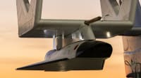
The second stage is the mid-course, cruise, and control phase. This stage has different requirements, such as monitoring the vehicle’s actuated surfaces. In general, the number of measurands decreases even though some are added for the actuator surfaces. Most COTS data acquisition products will support these measurands during this phase. However, the COTS products designed for fixed- and rotary-wing aircraft and missiles will need to be further ruggedized or qualified to hypersonic environmental conditions prior to installation and use on the platform.
In the terminal stage, the number of analog measurements is reduced even further, with an increase in measurements from digital buses (e.g., flight computers, time space and position information (TSPI) systems, and other mission systems that are part of the hypersonic platforms). In this case, the COTS data acquisition units need to be capable of supporting various bus types, e.g., serial interfaces, Ethernet, MIL-STD-1553, IEEE-1394, and ARINC-429.
The modularity of COTS data acquisition products enables hypersonic platform developers and integrators to construct specific combinations of data acquisition solutions for the different stages of the launch platforms.
Flight tests, especially hypersonic flight tests, are expensive. Therefore, end users and integrators typically overcompensate by increasing the number of measurements and specifying the environmental survivability to a much higher level than what is needed, resulting in increased flight test package cost and schedule demands. This result is more pronounced if the end user is using a custom FTI solution that has a fixed number of measurements. As programs mature, the required measurements will likely change, presenting complexity, qualification, and size, weight, and power challenges.
These challenges can be quickly addressed by ruggedizing existing COTS FTI products to the hypersonic environments, thereby preserving their modularity and leveraging their prior qualification pedigree.

Hypersonic Telemetry
After the data has been acquired, it must be transferred, or telemetered, over an RF link in real time. Some of the physics of the hypersonic environment pose unique challenges to this RF telemetry. For example, the disassociation and ionization of the air can result in an unpredictable RF channel. Also, because multistage platforms will encounter stage separation events, the plasma created behind it will result in a blackout period.
How does reliable flight test data get delivered to the ground stations during these blackout periods? One of the solutions that has been tested and proven for delivering reliable flight test data to ground stations is to acquire the data, store a certain amount, and then rebroadcast it later along with real-time data.
A data delay module allows a suitable delay time to be programmed, subject to any limitations due to the amount of memory available. Another approach is to request a rebroadcast of data from an onboard recorder using an uplink, or a command signal sent from the ground to the air. The last solution is to recover the recorder’s media cartridge post-mission for data analysis. This relies on the platform being intact on recovery or the storage media being crash-protected.
Link Margin and the Doppler Shift
One challenge for hypersonic flight test telemetry is the increased down range distance. Since the distances may be between 4,000 and 12,000 kilometers, a single line-of-sight RF link will not have the link margin to maintain reliable telemetry. One way to increase the link margin is to use forward error correction schemes, such as the low-density parity check (LDPC) and space-time coding. Forward error correction provides options to improve the link margin by reducing the required signal-to-noise ratio at the ground. Another option to provide coverage, especially if it is a depressed launch angle or glide path that is below the radar line of sight, is by using multiple receiving stations.
It is also important to consider the Doppler shift, as it presents a challenge for the receiver performance. While this issue is also present for fixed-wing and rotary-wing platforms, it is exacerbated at hypersonic speeds.
Encryption
Hypersonic RF telemetry data is likely sensitive, and data protection is needed. The technology that has been widely used in the U.S. is an NSA-issued encryption engine. However, this solution typically includes stringent schedule and program risk. Because of this, commercial AES encryption is becoming more popular. For onboard recording, the NSA’s Commercial Solutions for Classified program (CSfC) has defined several approved solutions for onboard recorders or data-at-rest applications.
For RF telemetry data-in-transit, some organizations have used AES-256 encryption. Custom solutions have been designed for streaming flight test telemetry using AES-256 encryption engines and include forward error correction to stream RF telemetry for all of the RF links.
Data Latency
Encryption can compound another issue: data latency within the FTI system. On the aircraft, this includes the delay introduced by data acquisition, PCM frame conversion, encryption, and RF-encoding. The delay from transmission to a display is based on the distance of the link and the processing time on the ground (including decryption, conversion into engineering units, and final distribution to ground operators).

The latency of the entire data chain, from the moment the measurand is sensed by the data acquisition module to the time the data is displayed to the ground operator, is not significant for rotor- or fixed-wing aircraft in terms of the distance flown during the latency period. However, for hypersonic platforms, the distance traveled during the data latency period may be significant. For example, a 3-second data latency translates to 21 km for a platform traveling at 7 km/s. During the final terminal phase before the platform crashes – the last data transmitted by the platform may be anywhere from a few milliseconds to seconds old due to the data latency within the airborne FTI network. Using FPGA, rather than software-based, systems can help by delivering lower and more deterministic latencies.
Another critical consideration due to latency is the flight termination or flight safety system. Traditionally, the flight termination system will have a human in the loop who will terminate the flight if it goes beyond the safety corridors. However, if the hypersonic platform exhibits erratic behavior and threatens inhabited areas, the ground controller will have very limited time to react and terminate the flight. Newer technology, such as an autonomous flight safety system (AFSS), will likely become the standard requirement for hypersonic flight tests. In an AFSS, an onboard system will monitor the vehicle’s location and issue a termination command when the vehicle’s path deviates from the planned flight path by more than a preset allowable deviation. Accurate location data from a TSPI system is vital for such a solution to operate effectively.
Conclusions
Hypersonic aircraft and ordinance developments are becoming more common, and the unique vehicle designs present several challenges for flight test applications. Many of these challenges can be addressed using existing hardware and techniques. Existing COTS components that are suitably ruggedized can be leveraged to meet and speed up environmental qualifications. Custom solutions to address unreliable RF channels, such as an acquired store and rebroadcast module or data retrieval on demand, have been proven. Error correction and encryption have also been used in the field. A range of flexible COTS architectures enable custom systems to be constructed, tested quickly, and adapted with minimal time to meet different program phase requirements.
This article was written by Ben Kupferschmidt, Senior Product Line Manager, Curtiss-Wright Defense Solutions (Ashburn, VA). For more information, visit here .
More From SAE Media Group
Tech Briefs
System for Flight Control of Hypersonic Aircraft
Tech Briefs
UCF’s Hypersonic Technology Advances
Aerospace & Defense Tech Briefs
Generation Orbit’s GOLauncher1 Is Officially the Air Force’s X-60A Hypersonic Flight Research Vehicle

Aerospace & Defense Tech Briefs
Raytheon, DARPA Push Forward with Hypersonic Weapon Design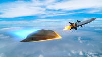
NASA Spinoff
Space Program Pumps Up Turbomachinery
Tech Briefs
Thin Film Sensor for Ultra High-Temp Measurement
Aerospace & Defense Tech Briefs
Pushing the Boundaries of Rapid Production of Spacecraft: Flight Results from NearSpace Launch’s TROOP and ThinSat Platforms
Aerospace INSIDER
Using Ultrabright X-Rays to Test Materials for Ultrafast Aircraft
Tech Briefs
Rapidly Evaluating Heat Shield Materials
Automotive Engineering
Bye Aerospace’s Solar-Electric Prototype Completes First Flight
Tech Briefs
How Jet Engine Flow Can Be Controlled Optically
Aerospace & Defense Tech Briefs
Air Force Receives First Joby eVTOL

Tech Briefs
Propulsion System for Hypersonic Flight
NASA Spinoff
Artificial Eyes Give Pilots a New Worldview

Aerospace & Defense Tech Briefs
Lockheed Martin and Arconic Collaborate on 3D Printing and Advanced Aerospace Materials
Aerospace INSIDER
Quarterhorse Hypersonic Test Aircraft Completes First Flight

Aerospace INSIDER
Hermeus Quarterhorse Joins Hypersonic High Cadence Testing Program
Tech Briefs
Foot Pedal Controller
Tech Briefs
Top 5 Videos of 2025
Aerospace & Defense Tech Briefs
NASA Budget Amendment to Help Send Americans to Moon by 2024, Then Mars
Aerospace & Defense Tech Briefs
AIA Predicts Flying Air Taxis, Supersonic Air Travel, and Space Industry for 2050
Aerospace & Defense Tech Briefs
A New Expanding NASA Aeroshell Could Mean Larger Planetary Payloads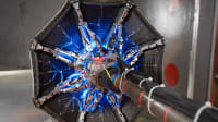
Aerospace & Defense Tech Briefs
SAE International Extends Call for Abstracts, Seeks Submissions for AeroTech Conference


Top Stories
INSIDERDefense
![]() New Raytheon and Lockheed Martin Agreements Expand Missile Defense Production
New Raytheon and Lockheed Martin Agreements Expand Missile Defense Production
NewsAutomotive
![]() Ford Announces 48-Volt Architecture for Future Electric Truck
Ford Announces 48-Volt Architecture for Future Electric Truck
INSIDERManufacturing & Prototyping
![]() Active Strake System Cuts Cruise Drag, Boosts Flight Efficiency
Active Strake System Cuts Cruise Drag, Boosts Flight Efficiency
ArticlesTransportation
![]() Accelerating Down the Road to Autonomy
Accelerating Down the Road to Autonomy
INSIDERMaterials
![]() How Airbus is Using w-DED to 3D Print Larger Titanium Airplane Parts
How Airbus is Using w-DED to 3D Print Larger Titanium Airplane Parts
Road ReadyTransportation
Webcasts
Electronics & Computers
![]() Cooling a New Generation of Aerospace and Defense Embedded...
Cooling a New Generation of Aerospace and Defense Embedded...
Power
![]() Battery Abuse Testing: Pushing to Failure
Battery Abuse Testing: Pushing to Failure
Connectivity
![]() A FREE Two-Day Event Dedicated to Connected Mobility
A FREE Two-Day Event Dedicated to Connected Mobility
Automotive
![]() Quiet, Please: NVH Improvement Opportunities in the Early Design Cycle
Quiet, Please: NVH Improvement Opportunities in the Early Design Cycle
Transportation
![]() Advantages of Smart Power Distribution Unit Design for Automotive &...
Advantages of Smart Power Distribution Unit Design for Automotive &...
Aerospace
![]() Sesame Solar's Nanogrid Tech Promises Major Gains in Drone Endurance
Sesame Solar's Nanogrid Tech Promises Major Gains in Drone Endurance