Key Measurements to Maintain Performance of Critical Electronic Systems on Military Aircraft and Warships
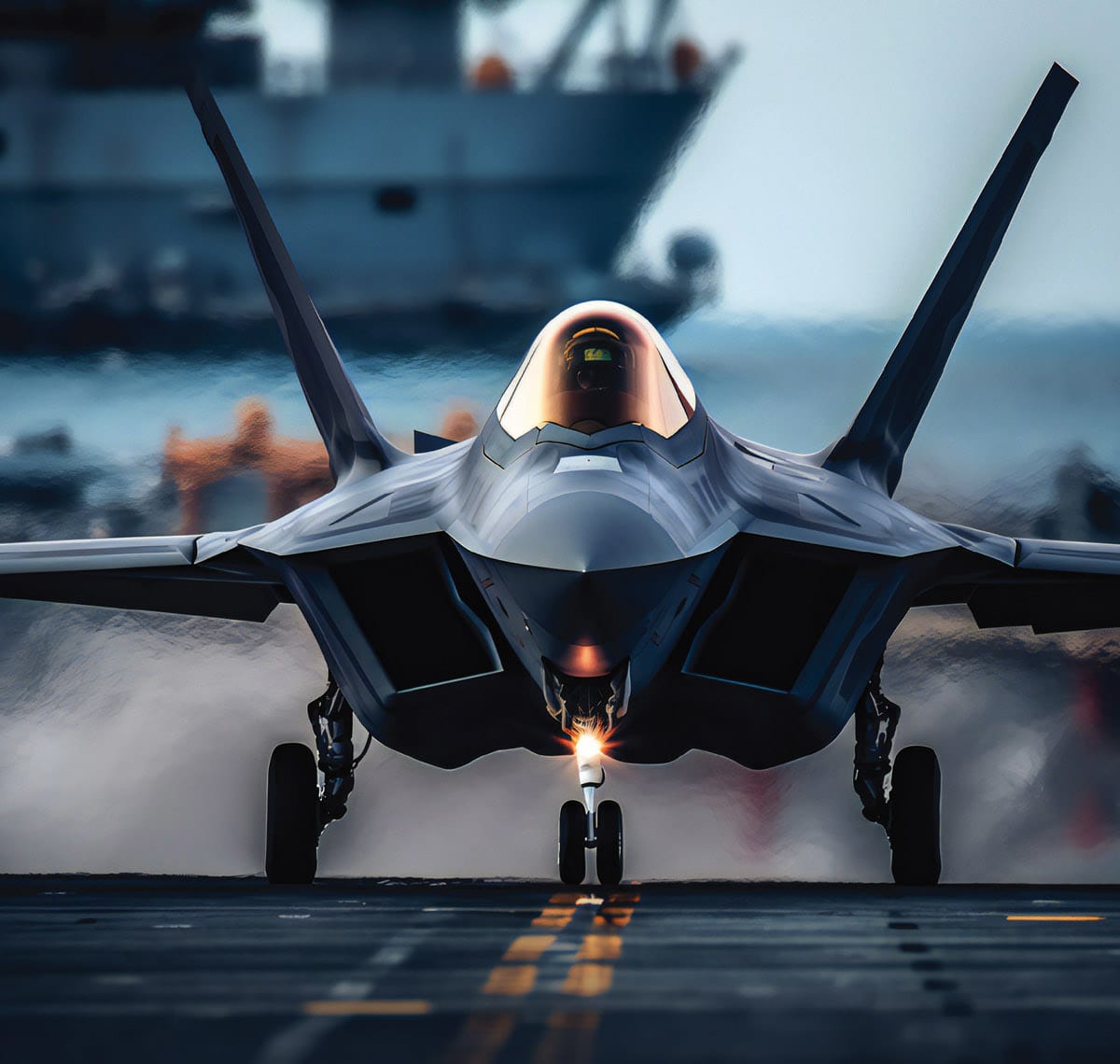
Modern armed forces require advanced signal transmission systems for mission success. Military operations, including those utilizing aircraft and warships, are reliant on receiving and transmitting high-speed data at RF and millimeter wave (mmWave) frequencies. In today’s battlefield, high-speed cables must perform to specification under any condition, which in turn necessitates innovative test solutions that can conduct accurate and repeatable measurements.
Mission success, aircraft survivability, and troop safety depend on critical defense systems. Signals intelligence (SIGINT), electronic warfare (EW), Command, Control, Communication, Computers, Cyber, Intelligence, Surveillance and Reconnaissance (C5ISR), and other systems must reliably provide global situational awareness. System interference can be caused by multiple factors – intentional and unintentional. Advancing EW technologies have led to an increase in nefarious acts by adversaries with the goal of intentionally creating interference. Because these systems operate in the most demanding environments, identifying, mitigating and preventing interference that can degrade performance is one of the biggest challenges.

Warship and Aircraft System Challenges
Measuring cable phase and magnitude performance over frequency becomes critical as systems become more sophisticated and complex. This is especially true in larger vehicles, such as aircraft and warships, where connections can be tens of meters in length.
In airborne applications, components of these critical systems are dispersed all over the aircraft for tactical or practical reasons. Many microwave/RF assemblies, power wires, and high-speed data cables are routed throughout the airframe to connect these components.
Cables used in typical aircraft are exposed to environmental and other hazardous contaminants. Once airborne, RF cables also experience repeated shock and vibration, extreme pressure, and temperature changes. Despite these conditions, cables must perform every time or aircrew and the entire mission are compromised.
Warships out at sea have their own set of challenges that affect cable performance. Shipboard systems are exposed to extreme and highly variable conditions, including heat or cold and corrosive salt spray. RF signals must travel through the cables at consistent speeds regardless of these environmental factors.
Repeated stress to cables during missions over time can lead to compromised signal integrity. The result is unreliable communications, degraded self-protection systems, lower mission completion rates, and increased lifecycle costs. Signal-to-noise ratio, low loss, and shielding are necessary so outside signals cannot interfere. All of this creates further challenges in determining the optimal coaxial cables and connectors for shipboard communications.
Testing Cabling on Large Vehicles
To maintain performance of these systems on large military vehicles, interference mitigation must be a priority. Often, vector network analyzers (VNAs) are used to ensure signal transmission.
Phase is a key parameter for detection and measurement in many shipboard RF systems to ensure continuous transmission and reception of RF signals with high accuracy and consistent speeds. There are two primary elements that can affect a coaxial cable assembly’s phase tracking characteristics – electrical length and temperature. As temperatures change, cables do not precisely track together. The result is degradation of phase match. Even a slight change can adversely affect system performance.
Fully characterizing long RF/μW cables once they are installed using vector S-parameter measurements creates a connection challenge between the VNA and the widely spaced cable ends. The interconnect cables required to connect the VNA ports to the cable under test add significant insertion loss and phase instability to the measurements over the distances involved. Cable replacement due to wear-and-tear adds considerable expense to the test setup, as well.
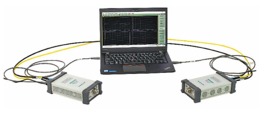
VNA architecture has evolved and can effectively address the challenges associated with large military vehicles. Some current VNAs have portable port modules that can connect directly to the cable under test. Figure 1 shows how cable measurements on ships and aircraft are made using this type of VNA. It is considerably different than a traditional VNA configuration, which requires additional test cables and connections that can create measurement uncertainty. Benefits of the modular portable port approach are shown in Table 1.

Eliminating EMI
With so much cabling and wireless equipment aboard large vehicles, electromagnetic interference (EMI) is a critical factor that must be considered, as well. EMI can cause equipment performance to degrade or even malfunction. Radios and radar signals are affected, as communications between the aircraft, ship, and command and control centers can be lost.
As a result, EMI effects must be considered in all aspects of systems utilizing RF cables. Standards such as RTCA DO-160 for environmental conditions and test procedures for airborne equipment or MIL-STD-461, developed by the Department of Defense (DoD) to control EMI issues, are often used as the basis of evaluation.
One key approach to prevent EMI is to provide shielding of various line replaceable units (LRUs) and harnesses. Shielding a device or system not only reduces EMI emissions, it improves susceptibility performance. With advances in wireless technology and increased device signal sensitivity, shielding becomes even more important to maintain the functionality and safety of equipment.
Benefits of Over-the-Air Testing
Engineers often use VNAs to test RF/μW shielding and propagation on large vehicles, as well. Typically, the configuration requires very long test port cables. At the distances required for these tests, coax cables introduce insertion loss and phase instability so significant that different transmission media, such as optical cabling, must be used to enable accurate S-parameter measurements. The additional hardware and setup complexity significantly increases the cost and time required to make the propagation and shielding measurements.
A modular chassis-less 2-port VNA with portable ports (figure 2) alleviates the additional expense and improves test times. Over-the-air (OTA) measurements on large vehicles can be more effectively conducted.
A VNA with modular, portable port design is well suited to perform measurements on wireless systems used on aircraft and warships. Its design allows for tests to be made using port modules up to 100 meters apart.
Conclusion
Wireless technology is a critical element of the modern battlefield, making accurate and consistent transmissions of high-speed data essential for mission success. Ensuring wireless system performance has additional challenges when implemented on warships and aircraft. A VNA architecture that allows test ports to be connected directly to each end of long cables in large vehicles optimizes dynamic range and improves phase stability in vector S-parameter testing, for greater confidence in system performance in mission-critical applications.
This article was written by Pete Alexander, Business Development Manager at Anritsu Company. For more information, visit here .
Top Stories
INSIDERRF & Microwave Electronics
![]() FAA to Replace Aging Network of Ground-Based Radars
FAA to Replace Aging Network of Ground-Based Radars
INSIDERManned Systems
![]() F-22 Pilot Controls Drone With Tablet
F-22 Pilot Controls Drone With Tablet
Road ReadyTransportation
![]() 2026 Toyota RAV4 Review: All Hybrid, All the Time
2026 Toyota RAV4 Review: All Hybrid, All the Time
INSIDERSoftware
![]() Algorithms for Autonomous Marine Vehicles
Algorithms for Autonomous Marine Vehicles
INSIDERDefense
![]() L3Harris Starts Low Rate Production Of New F-16 Viper Shield
L3Harris Starts Low Rate Production Of New F-16 Viper Shield
INSIDERMaterials
![]() New 3D-Printable Nanocomposite Prevents Overheating in Military Electronics
New 3D-Printable Nanocomposite Prevents Overheating in Military Electronics
Webcasts
Energy
![]() Hydrogen Engines Are Heating Up for Heavy Duty
Hydrogen Engines Are Heating Up for Heavy Duty
Energy
![]() SAE Automotive Podcast: Solid-State Batteries
SAE Automotive Podcast: Solid-State Batteries
Energy
![]() SAE Automotive Engineering Podcast: Additive Manufacturing
SAE Automotive Engineering Podcast: Additive Manufacturing
Defense
![]() A New Approach to Manufacturing Machine Connectivity for the Air Force
A New Approach to Manufacturing Machine Connectivity for the Air Force
Automotive
![]() Optimizing Production Processes with the Virtual Twin
Optimizing Production Processes with the Virtual Twin
