


More Electric, Integrated Fuel Systems
Engine system reliability can be improved by advanced electric architectures, while the reduction of hydraulic components, fuel tubes, and fittings can enhance the maintainability of the engine and minimize pilot workload.
Global warming and environmental friendliness considerations have recently been key for multiple global industries. In the commercial aviation industry, reduction of aircraft emissions, including CO2 and noise, is an urgent priority. Both aircraft and aircraft engine manufacturers are striving to improve design to accommodate the needs of commercial airlines. Engine manufacturers in particular have worked long and hard to improve each engine component, e.g., compressors, turbines, combustors, etc.

The MEE is a new engine system concept that seeks engine efficiency improvements, which results in a reduction of engine fuel burn and CO2 emissions. The key concept of the MEE system involves the architecture for the electrical power generation by the engine and changing the power source for accessories from mechanical/hydraulic to an electric motor.
IHI focused on the electrification of the engine fuel pump system because of its contribution to fuel burn reduction. The researchers conducted a feasibility study of the MEE fuel system for an assumed small-size turbofan engine, and the result indicated an improvement in specific fuel consumption (SFC) by about 1% during cruising. The SFC improvement would be accomplished by removing the fuel bypass circuit and eliminating the ACOC (aircooled oil cooler), which worsens engine efficiency.
There are several technical challenges for the practical design of the MEE motor-driven fuel pump system. Failure of the engine fuel pump may induce IFSD (in flight shut down) of the engine and result in catastrophic failure of the aircraft. To avoid such critical situations and ensure better reliability than that of the conventional system, a fault-tolerant design of the electric drive is mandatory.
In addition, IHI proposed the introduction of advanced fault-tolerant technologies such as a unique active-active redundant motor control system to the MEE. The active-active control enables the supply of the same amount of fuel to the engine combustor in case a single open failure occurs in one of the redundant motor systems.
Conventional vs. MEE Fuel Systems


One typical example of a segregated system is the engine fuel system. It is independent from the aircraft fuel system and both systems are designed to accommodate various conditions, which are designated at the interface point between aircraft system and engine inlet. Integrating the aircraft and engine fuel system would be helpful to construct a more efficient and simplified system, but it seems not to be practical in the conventional aircraft system.
The aircraft system contains electric motor-driven fuel boost pumps, shutoff valves, and cross feed valves as a minimum. There may be fuel transfer pumps, such as electric motor-driven pumps or ejector pumps, for transferring fuel between the tanks. In the case of a twin engine aircraft, the left- and right-hand engines are supplied with fuel from the left and right wing tank, respectively, during normal operation. If IFSD occurs in one of the engines, the cross feed valves would be activated to supply fuel from the opposite side tank to avoid an imbalance of fuel mass.

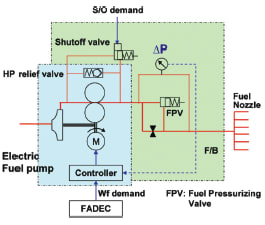
Typically, the fuel pump consists of an LP (low pressure) impeller pump and HP (high pressure) gear pump. The LP pump increases fuel pressure at the HP pump inlet for the proper suction of fuel.
A more electric architecture supports the integration, simplification, and reconstruction of the aircraft and engine fuel system because of increased controllability, a modular design, and flexibility of component installation.
The MEE electric fuel system simplifies the engine fuel system by eliminating the fuel bypass circuit and complicated FMU. In addition, the MEE fuel system increases the flexibility of the engine fuel pump installation, because it is not necessary any more to attach the motor-driven fuel pump to the engine AGB. The location of the pump may be moved to an area other than the external surface of the engine. It means that the engine fuel pump is possibly considered as one of the components within the aircraft fuel system, and a possible location would be in the nacelle, fuselage, or wing.
Current aircraft fuel systems and engine fuel systems have duplicated functions, such as a boost pump, which enables the provision of proper suction of fuel from the tank, and a shutoff valve that shuts off fuel to the engine combustor. An integrated fuel system would remove the burden of the aircraft and engine interface condition, removing the duplicated function as much as possible and simplifying the system construction.
Integrated Fuel System Benefits

Also, the number of components in the fuel system would be minimized. In the conventional aircraft fuel system and engine fuel system, which are separated from each other, there is a duplicated function between the aircraft components and the engine components. One of the typical examples is the pressure boosting function to ensure that the engine fuel pump properly suctions fuel from the aircraft fuel tank.
In the conventional system, electric motor-driven fuel boost pumps, which are usually submerged in the fuel tank, pressurize fuel to provide the minimum pressure required by the engine fuel system. Typically, the aircraft boost pump is the impeller type and adds about 50 psi to the tank pressure. However, the engine fuel pump also has a LP impeller pump to boost fuel pressure at the engine inlet because the engine fuel pump is required to supply fuel even though the aircraft boost pump is in operational condition.
In the proposed integrated system, the boosting function is accomplished by the LP impeller pump in the electric fuel pump unit. The feasibility study of the small-size turbofan MEE fuel pump shows that the single shaft electric pump, which drives both the LP impeller pump and HP gear pump by the same shaft, can suction fuel during an aircraft boost pump failure. The submerged aircraft fuel boost pumps can be removed, which will not only contribute to a reduced number of components, but also remove the submerged components in the fuel tank.
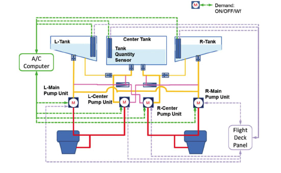
Another possible approach to reduce the number of components is to remove the cross feed valves and electric transfer pumps. In a conventional fuel system, the cross feed valve is necessary to have fuel mass balance between the left and right wing tanks in case one of the engines is shut down. In the proposed integrated fuel system, the left main pump unit has fuel inlets connecting to both left and right wing tanks. It is the same for the right main pump unit. The left and right main pump units always suction fuel from both the left and right wing tanks, so the fuel mass balance between the tanks will be maintained automatically, allowing the cross feed valve to be removed.
In the integrated fuel system study for an assumed single-aisle aircraft, it was estimated that the aircraft boost pumps, engine FMUs, and MFPs (main fuel pumps) in the conventional system would be replaced by four sets of electric fuel pump units. In addition, with the cross feed valves and aircraft shutoff valves removed, the total number of LRUs (line replacement units) in the integrated aircraft system is expected to be reduced to about half of the conventional system.
The proposed integrated system eliminates electric valves such as the cross feed and shutoff valves as much as possible. However, in considering emergency situations—for example, severe fuel leakage from anywhere in the system—isolation of the fuel system may be required to avoid loss of the aircraft fuel. For that purpose, the addition of monitoring devices such as fuel pressure sensors, leak detectors, and electric shutoff valves may be considered. Also, if the aircraft system wants to control the fuel amount in the left and right tanks independently, that would be accomplished by the addition of the electric shutoff valves in the system. Thus, the proposed integrated electric fuel system has the flexibility to incorporate additional electric devices and will support aircraft system requirements.
As mentioned above, the reduction in the number of LRUs will be achieved by introduction of the integrated fuel system. In addition, components that are submerged in the aircraft fuel tanks, such as the aircraft boost pumps, will be removed. One possible location for the electric fuel pump units is the fuselage, inside of the access door.
Currently, LRUs are installed into distributed locations among the aircraft wing, aircraft tank, and the engine. In the integrated system, the LRUs may be installed in one place in the aircraft fuselage, so that replacement of the pump unit will be much easier than the current aircraft/engine fuel system components. Reduction in the number of LRUs, accessibility, and replaceability of the electric pump unit will improve the maintainability of the aircraft/engine fuel system.
Because the integrated system allows for the removal of the cross feed valves, adjustment of the tank balance by pilots would not be necessary anymore. On/off of the current submerged aircraft boost pumps is usually conducted by pilots to maintain a minimum amount of fuel in the tank, which is previously determined to avoid heating of the pump.
In the proposed integrated fuel system, the electric fuel pump units would be installed outside of the fuel tank, instead of the submerged boost pumps. Pilot operation for the cross feed valves or boost pumps would not be necessary; thus, reduction of pilot workload would be expected.
This article is based on SAE International technical paper 2013-01-2080 by Noriko Morioka IHI Corp. and Hitoshi Oyori, IHI Aerospace Co.
More From SAE Media Group
Aerospace & Defense Tech Briefs
Hybrid-electric distributed propulsion explored
Aerospace & Defense Tech Briefs
Ceramic Matrix Composites in Aircraft Engines Projected to Double over Five Years, Stratview Research Predicts
Aerospace & Defense Tech Briefs
Parker Aerospace and GKN Aerospace to Develop Passive Cooling Solutions for Next-Generation Aircraft Engines
Tech Briefs
Novel Turboelectric Aircraft Design
Aerospace & Defense Tech Briefs
New Research on Noise Reduction for Next Generation Aircraft Engines
Tech Briefs
High-Temperature Ni-Based Superalloy Composition
Aerospace & Defense Tech Briefs
Zwick Roell Provides Flexible Materials Testing over a Wide Temperature Range
Aerospace & Defense Tech Briefs
Government, Industry Invest $450M to Advance U.K. Civil Aerospace Research, Technology, Manufacturing
Aerospace & Defense Tech Briefs
Thermostatic Solutions for Temperature Control Applications
Aerospace & Defense Tech Briefs
UAV Fuel Management System
Aerospace & Defense Tech Briefs
Industry Invited to Participate in AeroTech Aerospace and Defense Technical Program
Aerospace & Defense Tech Briefs
2050 Aircraft Engine Designs Go Radical, Part 2
Aerospace & Defense Tech Briefs
Cold Spray Technology
Aerospace & Defense Tech Briefs
2050 Aircraft Engine Designs Go Radical, Part 1
Tech Briefs
Thermal Bypass Valves
Tech Briefs
2025 Award Finalists

Aerospace & Defense Tech Briefs
Hybrid Auxiliary Propulsion System
Aerospace & Defense Tech Briefs
Designing a Power Generation System for a More-Electric Aircraft

Aerospace & Defense Tech Briefs
Lockheed Martin and Arconic Collaborate on 3D Printing and Advanced Aerospace Materials

Off-Highway Engineering
Liebherr Reveals ‘Hybrid’ CFRP Cylinders and Parallel-Pump Concept
Aerospace & Defense Tech Briefs
Vacuum Regulators to Simulate Altitudes
Tech Briefs
Meringue-Like Material Reduces Aircraft Noise
Aerospace Manufacturing and Machining INSIDER
GE Concludes Phase 1 Testing on XA100 Adaptive Cycle Engine
Aerospace & Defense Tech Briefs
Fanjet Evolution — the Next Steps

Tech Briefs
UCF’s Hypersonic Technology Advances
Top Stories
INSIDERMaterials
![]() How Airbus is Using w-DED to 3D Print Larger Titanium Airplane Parts
How Airbus is Using w-DED to 3D Print Larger Titanium Airplane Parts
INSIDERAerospace
![]() FAA to Replace Aging Network of Ground-Based Radars
FAA to Replace Aging Network of Ground-Based Radars
NewsUnmanned Systems
![]() CES 2026: Bosch is Ready to Bring AI to Your (Likely ICE-powered) Vehicle
CES 2026: Bosch is Ready to Bring AI to Your (Likely ICE-powered) Vehicle
NewsSoftware
![]() Rewriting the Engineer’s Playbook: What OEMs Must Do to Spin the AI Flywheel
Rewriting the Engineer’s Playbook: What OEMs Must Do to Spin the AI Flywheel
Road ReadyTransportation
![]() 2026 Toyota RAV4 Review: All Hybrid, All the Time
2026 Toyota RAV4 Review: All Hybrid, All the Time
NewsSoftware
Webcasts
Automotive
![]() E/E Architecture Redefined: Building Smarter, Safer, and Scalable...
E/E Architecture Redefined: Building Smarter, Safer, and Scalable...
Transportation
![]() Hydrogen Engines Are Heating Up for Heavy Duty
Hydrogen Engines Are Heating Up for Heavy Duty
Automotive
![]() Advantages of Smart Power Distribution Unit Design for Automotive...
Advantages of Smart Power Distribution Unit Design for Automotive...
Automotive
![]() Quiet, Please: NVH Improvement Opportunities in the Early Design...
Quiet, Please: NVH Improvement Opportunities in the Early Design...
Power
![]() A FREE Two-Day Event Dedicated to Connected Mobility
A FREE Two-Day Event Dedicated to Connected Mobility
Power
![]() Powering America’s EV Future: Connect, Collaborate, Innovate
Powering America’s EV Future: Connect, Collaborate, Innovate