


Designing a Power Generation System for a More-Electric Aircraft
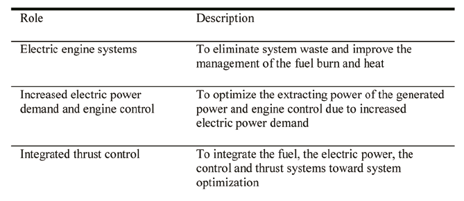
It is theorized that systems and equipment for an All Electric Aircraft (AEA) will be developed 20 years hence as a More-Electric Aircraft (MEA) with no bleed system, which is a concept typified by the Boeing 787, and electric powered propulsion (including electric distributed thrust or electric hybrids by gas turbine power generation), which is expected to be realized after the 2040s. In this trend, a More-Electric Engine (MEE) plays the roles shown in Table 1.
 A conventional engine has two responsibilities: propulsion as a primary function, and a power plant for the secondary systems power source as a subsidiary function. This article will focus on the expectation that MEE will be provided as a future key technology for the total energy management of MEA. Specifically, the engine will be an important factor not only for the conventional role of high efficiency and low emission, but also for optimization between the propulsion system and electric power system because an MEA integrates power management into the electric power generated by engines. In addition, the MEE will also have to consider the importance for optimization of the aircraft in integrated management by advancing management of fuel burns and the thermal control system, optimization of engine control and information sharing with the entire aircraft, and the integration of flight control.
Low-Pressure Spool Power Generation
A similar design concept must also be considered for the power supply of the electric system. Although a starter/generator realized by the high power of the aircraft's generator contributes to the reduction of the conventional air starter and plumbing, it is considered a transfer mechanism that may become larger due to increased extraction of power by a power take-off as the secondary power, which was bled of air, replaced with electrical power by an engine-driven generator, disposal of the generated heat by the enlarged starter/generator, and the limitation of location and available space around an engine.
Electric Power Demand and Engine Control

The power generation system is necessary for the engine system considering the improvement of generating efficiency for future increased power demand, stability of engine control, and limits of mounting structures of an extraction mechanism and generators. General aero-engines have a low-pressure (LP) spool and high-pressure (HP) spool in the compressor and the turbine, respectively, and fans that acquire thrust are driven by a low-pressure shaft and the generator and the pumps are driven by the torque of a high-pressure shaft. The generator drive by the torque of a low-pressure shaft should be examined in consideration of weighing up the merits and demerits of the high-/low-pressure shafts shown in Table 2.
Integrated Propulsion Control
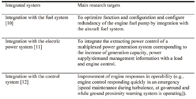
Tightening the information and communication between the control system of MEE and the aircraft system may enable integrated control such as removing limiting conditions temporarily by analysis of the information and the status in coordination with engine control and aircraft control in an emergency. Coexistence of aircraft control, electric power management and stability of engine operation must function as total energy management at normal times and provide safety and stability in an emergency (Table 3).
As described, the MEE shares a close working relationship with the MEA and the AEA in every aspect. While the MEE, especially the electric fuel system, is thought to play an important role in thermal management and control of electric aircraft in the future, it is also an essential system as well as a flight control system and requires high reliability and safety.
Sufficient Emergency Power
For example, the ram air turbine (RAT) system has covered essential power supply and the flight control drive for conventional aircraft in an emergency, but it may not be enough for the AEA due to increased power demand. The auxiliary power unit (APU) is also not sufficient to back up the AEA because it has a failure mode as common as the engines, such as a disabled fuel system. Therefore, alternative energy sources such as batteries and fuel cells (FC) will be required. In that case, the problem is specific energy performance and it is difficult to mount those batteries and fuel cells due to the weight. Taking this into consideration, we’ve focused on an LP power generation system as a high-performance emergency source.
Definitions of Power System Operation
Electric Power Demand for Emergencies
There are two modes of power supply system operation: ground operations and in-flight operations.
In terms of emergency and recovery operations, first, it should be determined whether at least one or more engines work correctly, or if both engines of a twin-engine aircraft are down in an emergency situation. If one or more engines work correctly, the capacity of the engine generators are thought to be designed to basically enable normal operation. In these cases, the following need to be satisfied from the requirements of each certification.
The Control System can be Operated and the Aircraft Can Fly and Land Safely Even if Two Engines are Broken
Applicable requirement;
CFR(Code of Federal Regulation) Title 14, Part25,
Subpart D - Design and Construction, CONTROL SYSTEMS,
§ 25.671 General. (d)
In this condition, electric power must be provided to the avionics, the flight control, a high lift device so that communication, position and attitude, attitude control and lighting is complete, but not to the ECS, the galley, the fuel pumps (the engines are already down), on-board entertainment, anti-icing systems (it was impossible for conventional aircraft to provide the electric power while the engines were down because bleed air was used).
The Engines Can Restart at a High Altitude Even if the Normal Power System Cannot be Used
Applicable requirement; CFR Title 14, Part25,
Subpart D, ELECTRICAL SYSTEMS AND EQUIPMENT,
§ 25.1351 General. (d)
The starter/generator needs to be used for engine restart, which consumes a lot of electric power. Since the time to restart the engines is short, electric power is provided only to the communication system, the attitude indicator, the attitude control and the fuel pumps but not to all other nonessential and non-urgent-use equipment. After restarting the engines, all the systems are restored immediately.
The ETOPS Should be Satisfied Even if a Triple Fault in the Electric Power Equipment Occurs
Applicable requirement; CFR Title 14, Part25, Subpart I - Special Federal Aviation Regulations, APPENDIX K TO PART 25-EXTENDED OPERATIONS (ETOPS),
K25.1 Design requirements.
K25.1.3 Airplane systems. (b)
K25.1.4 Propulsion systems. (a)
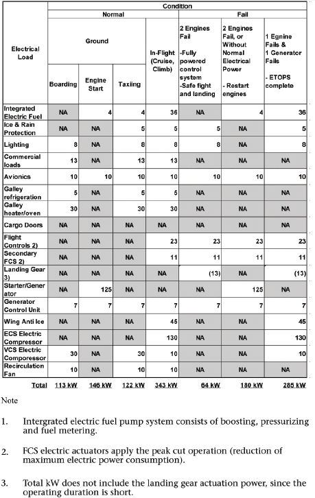
Electric power is supplied to the communication system, the attitude indicator, the attitude control system, the lighting, the fuel pumps and anti-icing systems so that normal operation is available with one engine. Table 4 shows the calculated result of the necessary electric power of a single aisle aircraft with 180 seats based on the above conditions. Power demand for each electrical load was estimated assuming the 180-seater AEA system.
The Peak Cut Operation
It is necessary to reduce the electricity in an emergency and the electric power for the flight control is estimated at approximately less than 30% of the maximum electric power by the foregoing calculations. For the AEA, all actuators for flight control are electric and the electric power system is required to provide peak current and absorb regenerated current repeating powering and regeneration according to the control surface operation. Especially, when the peak current is provided from the power supply, the capabilities of the power system affect not only the generator capacity and size but also the wire capacity and weight to prevent a voltage drop by line impedance.

A capacitor, which saves electric charge in the inductor, is generally applied for the electric accumulator; however, FWB, which saves the power by kinetic energy, is superior for an application requiring both high power and energy. FWB is also highly effective by being located close to the load whenever possible and therefore, superior to the capacitor, which is inferior in low temperature characteristics, considering its mounting on a non-pressurized area. In addition, it is considered that both the leveling and high reliability of the electricity can be achieved by making use of the feature that FWB can transmit the electricity and energy insulating electrically through kinetic energy and configuring to distribute the electricity to multiple control surface actuators from the multiplexed power system.
System Configuration
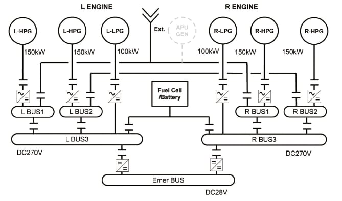
This system is comprised of the combination of the conventional HP-SPOOL power generation and LP-SPOOL power generation. LP power generation is available to provide more electric power than the HP power generation at the time of the engine halting, which means a windmill condition in flight. It is expected that LP power generation can be used as an alternative power generation system without mounting the RAT by adding the same function as RAT to it. The FC (Fuel cell) is a part of the configuration as an alternative system to the APU, but a large weight disadvantage is caused when the FC is requested to generate the same volume of power as the APU. Therefore, the important point of this study is to discuss how much the output of the FC can be reduced with the combination of LP power generation assuming the operational situation.
System Distribution
The system distribution of a single aisle aircraft with 180 seats is described. We assume 400kw electric power generation per engine through the combination of two HP-SPOOL power generations of 150kw × 2 and one LP power generation of 100kw, considering the function redundancy of the starter for the conventional HP-SPOOL power generation. Confirming the conformity by each condition, given that a windmill power generation of the LP generator is 1/2 the rated capacity (assumed value), it is found that mounting an FC rated about 80kw enables operation.
According to the current FC system for aviation, the weight is about 200kg per 25kw. Therefore, approximately 600kg- 800kg composition is assumed. Given that the RAT weighs 200kg including the structure and the APU weighs 200kg (including fuel), the weight is increased by about 200kg-400kg. Since, on the ground, the engines need to be started only with the power from the FC, the FC must tolerate about twice the rating for power supply for a short time for engine starting, which should be taken into consideration for the thermal design of fuel cells.
There are several approaches to developing this power source. The existing high-power ratio HEV lithium-ion battery (LIB) is 25 kg at a 30 kW rate (1.4Wh). If we assume a power source capable of 150 kW, the LIB system weight would be 125 kg. This LIB would also incorporate the engine starter current design specifications. However, this LIB system limits the time to operate the engine starter. The LIB system stores the 7.0Wh at 150kW output power and approximately 170-second run times.
Challenges of Generating Power by a Low-Pressure Shaft
The capacity of LP power generation affects the feasibility of the FC.The challenges of generating power with the low-pressure shaft as opposed to the more common high-pressure shaft, are:
- Type of generator
- Location of the generator
- Proposal for a new aircraft electric power system
The specific difference between a generator driven by a low-pressure spool and that driven by a high-pressure spool is rotation speed range. The rotation speed of a high-pressure spool for general aero-engines changes within the range of 60-100%, but that of a low-pressure spool changes within the range of 20-100%. For the generator of the highpressure shaft, a field winding-type synchronous type is broadly used, but it is not suitable for power generation by a wide rotation speed range because a built-in permanent magnet generator is used as a field power supply and output voltage is in proportion to the rotation speed cubed in principle.

The current generator of the high-pressure spool is mounted on an AGB (Accessory Gear Box). The generator of the low-pressure spool is considered to be embedded and directly linked to the engine shaft in an aft-sump space or a front-sump space, in addition to mounting on the AGB as well as that of the high-pressure shaft, and considering the reduced mounting space around a fan due to a high bypass ratio and AGB-less for any future plan. The aft-sump area (tail cone) has a large mounting space but has a relatively high temperature. On the other hand, the front-sump area is limited in mounting space. The method to mount on the AGB is thought to be an extension of the conventional technique and has fewer challenges, but the increased weight by larger PTO (Power Take-Off) and the influence on engine performance by the decreased area for air flow in the engine need to be examined.
The maximum rotation speed of the low-pressure spool is about 1/3 that of the high-pressure spool. Since the constitution of generators become larger as rated speed becomes lower if they have the same output/method, the generator of the low-pressure spool will become larger than that of the high-pressure spool. Although it can be smaller by adding a gear and accelerating, the acceleration is limited by the magnetic saturation characteristic of the magnetic body and mechanical strength. In addition, since the efficiency of the generator becomes lower, the fluctuation range of the efficiency by the rotation speed becomes large for the generator of the low-pressure shaft that has a wide range of rotation speeds. Since the generator of the low-pressure spool is inferior to that of the high-pressure spool in performance and efficiency, it is practical to think this for the relatively low power. For a test calculation, the volume is set based on an assumption that a 100kw generator is realistic.
Future Challenges
Downsizing and lightening is the most challenging matter and downsizing of power electronics using a fuel cell and wide band gap elements is an essential technique. Downsizing and lightening of generators is also important. For the future, since lightening is important to realize LP power generation, research is expected to move toward an electric motor with high temperature tolerance that can operate under temperatures of more than 400°C for LP power generation, aiming at a composition to mount the LP power generator on an AFT-sump that does not require a PTO shaft.
This article is based on SAE Technical paper2015-01-2408 by Hitoshi Oyori, IHI Aerospace Co. Ltd., and Noriko Morioka and Tsuyoshi Fukuda, IHI Corporation, doi:10.4271/2015-01-2408.
More From SAE Media Group
Aerospace & Defense Tech Briefs
Electrically Driven General Systems for UAVs
Aerospace & Defense Tech Briefs
Industry Invited to Participate in AeroTech Aerospace and Defense Technical Program

Aerospace & Defense Tech Briefs
SAE International Extends Call for Abstracts, Seeks Submissions for AeroTech Conference
Off-Highway Engineering
Battery Innovation Key for Commercial and Off-Highway EVs
Aerospace & Defense Tech Briefs
Engineering an Aircraft Hydrogen Powertrain
Aerospace & Defense Tech Briefs
Hybrid-electric distributed propulsion explored
Aerospace & Defense Tech Briefs
Hybrid Electric EWIS System

Aerospace & Defense Tech Briefs
Power Management for the Electric Taxiing System Incorporating the More Electric Architecture
Tech Briefs
Propelling the Future of Sustainable Aviation
Aerospace & Defense Tech Briefs
SAE International Issues, Revises Technical Reports for Aerospace Engineering
Off-Highway Engineering
Kalmar Launches 3rd-Gen Electric Terminal Tractor
Tech Briefs
A Heat Engine with No Moving Parts
Aerospace & Defense Tech Briefs
More Electric, Integrated Fuel Systems
Off-Highway Engineering
Challenges and Opportunities of Electrifying Off-Highway Machines
Off-Highway Engineering
GM Hydrotec Boss Readies Fuel Cells for Commercial Deployment
Automotive Engineering
For Aptiv, More EVs Mean More Profit with SVA
Aerospace & Defense Tech Briefs
Lilium Starts Production of eVTOL Jet Batteries
Off-Highway Engineering
Battery of Issues Surrounds Large-Vehicle Electrification
Off-Highway Engineering
Perkins Expands Power Generation Powertrain Lineup
Aerospace & Defense Tech Briefs
Weapon and Armor System Power in Future Combat Vehicles
Tech Briefs
Fuel Cell Boosts Electric-Powered Vehicles
Aerospace & Defense Tech Briefs
Bringing Turbine Power to Small Aircraft
Motion Design
High-Efficiency Megawatt Motor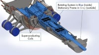
Off-Highway Engineering
Addressing Electromagnetic Compatibility in the Context of Aircraft Electrification
Aerospace & Defense Tech Briefs
Zero-Emissions Electric Aircraft: Theory vs Reality

Automotive Engineering
Suppliers Prepare for a Drop in EV Market Share
Off-Highway Engineering
Fuel Cell Production Spurs Supplier Opportunities
Top Stories
INSIDERManufacturing & Prototyping
![]() How Airbus is Using w-DED to 3D Print Larger Titanium Airplane Parts
How Airbus is Using w-DED to 3D Print Larger Titanium Airplane Parts
INSIDERManned Systems
![]() FAA to Replace Aging Network of Ground-Based Radars
FAA to Replace Aging Network of Ground-Based Radars
NewsTransportation
![]() CES 2026: Bosch is Ready to Bring AI to Your (Likely ICE-powered) Vehicle
CES 2026: Bosch is Ready to Bring AI to Your (Likely ICE-powered) Vehicle
NewsSoftware
![]() Accelerating Down the Road to Autonomy
Accelerating Down the Road to Autonomy
EditorialDesign
![]() DarkSky One Wants to Make the World a Darker Place
DarkSky One Wants to Make the World a Darker Place
INSIDERMaterials
![]() Can This Self-Healing Composite Make Airplane and Spacecraft Components Last...
Can This Self-Healing Composite Make Airplane and Spacecraft Components Last...
Webcasts
Defense
![]() How Sift's Unified Observability Platform Accelerates Drone Innovation
How Sift's Unified Observability Platform Accelerates Drone Innovation
Automotive
![]() E/E Architecture Redefined: Building Smarter, Safer, and Scalable...
E/E Architecture Redefined: Building Smarter, Safer, and Scalable...
Power
![]() Hydrogen Engines Are Heating Up for Heavy Duty
Hydrogen Engines Are Heating Up for Heavy Duty
Electronics & Computers
![]() Advantages of Smart Power Distribution Unit Design for Automotive...
Advantages of Smart Power Distribution Unit Design for Automotive...
Unmanned Systems
![]() Quiet, Please: NVH Improvement Opportunities in the Early Design...
Quiet, Please: NVH Improvement Opportunities in the Early Design...