


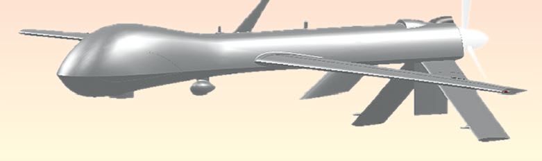
Airflow and Thermal Analysis of UAV De-Icing Systems
The use of unmanned aerial vehicles (UAVs) has been increasing around the world as many countries have been rapidly adding UAVs to their arsenals during the past decade. One of the most critical challenges facing UAV designers is icing. Icing has long been known to be dangerous for aircraft. A pilot, though, can recognize icing conditions and compensate for them by either activating de-icing systems or by adjusting to the changing flight characteristics of the aircraft and removing the aircraft from the icing conditions. The current generation of US Military UAVs deployed in Afghanistan had issues with icing that caused many crashes, costing millions of dollars. This led to the development of UAV design variants with deicing systems.
Computational Flow Dynamics
A design engineer, however, needs to be able to simulate a design in all operating conditions and configurations to gain the most insight. CAD-embedded CFD allows fast, accurate CFD simulations on existing CAD geometry, and knowledge of the numerical methods used in complex CFD analysis isn’t necessary.
Imagine the scenario that likely played out when these UAVs started having icing problems. First, senior management was notified who passed the issue over to the engineering managers, who would then bring together an engineering team to design a remedial solution. The engineers would be working to understand the issue as well as many different de-icing systems, each with its own pros and cons.
Because UAVs are surveillance aircraft designed to remain in the air for long periods, any de-icing system must be as light as possible to maintain fuel efficiency. At this point, CAD-embedded CFD can save the UAV manufacturer a lot of money. By simulating the different design options at an early stage, the engineers can eliminate the wrong design paths early before a significant amount of engineering time has been spent working on dead-end designs and it can more quickly narrow the engineering focus onto the designs that will work.

Sample Systems
Let’s look at three examples of how CAD-embedded CFD would help in analysis of three different de-icing systems.
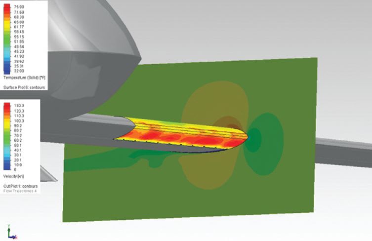
The first de-icing system involves placing electrical heating elements in the leading edge of the wing. These systems have been around since the 1940s, and they operate by heating up the surface above the melting point of the ice. Modeling this with the CADembedded CFD software was very simple. All that was needed was to split the surface to create the leading-edge zone where heat would be applied.
The CAD-embedded CFD analysis showed that while the surface where the heating was applied was kept above the freezing temperature, behind the leading edge of the wing was a different story. The original assumption was that the heating element would cause a heated boundary layer that would protect the rest of the wing. Further CFD simulations showed that to achieve that, the front surface would have to be >100 °F and would require ~2,700W of energy to have warm air cover the 2.4 ft. wing section used for the simulation (Figure 2).

Another similar concept for a de-icing system was developed by design engineers at Kelly Aerospace called the ThermaWing™ [*]. The elements of the system are basically the same. It uses electrical heating elements on the surface, except that they are separated into two zones. Right on the very front of the wing is the always-warm zone. Behind this, a secondary heating zone is created by cycling heating on and off. Once a layer of ice has formed, the heater is cycled on. The secondary zone heater doesn’t have to melt all the ice; it just melts a thin amount of ice at the surface. Once a thin film of water has been created between the surface and the rest of the ice, the bond between the ice and wing is broken and the ice will be shed. Then the cycle repeats. This system seems like it would be more energy efficient because it isn’t on continuously.
For analyzing this design with the CADembedded CFD software, the wing surface was split into three zones: the alwaysheated zone, the periodically heated zone, and the aft unprotected zone. A block of ice also had to be modeled on top of the wing surface, which was assumed to be 5mm thick. All these geometry changes were quick and easy to make in the CAD system. The analysis was set up to be a transient simulation, with the secondary heater turned on at t = 0.
The results showed that this system would work and requires less energy than the previous system at ~1,200 W when both heating zones are activated for the test section. Since the majority of that energy is used periodically for the secondary heating area, the time averaged energy use would be much lower, but the cycle rate would depend on the ice accumulation rate so averaged power dissipation was not calculated. The CADembedded CFD simulation showed the average temperature of the ice-to-wing surface interface reaches its melting temperature at about 1 second, the exact amount of time claimed by Kelly Aerospace in their literature. Figure 3 shows the temperature results.
A third de-icing design analyzed here is a heated air tube system, in which pressurized hot air is sent through a tube that runs under the surfaces that are to be heated. The tube has holes to spray the hot air onto the surfaces. Typically, this hot air is provided by air bleed from the gas turbine engine. The UAV in this case has a piston engine, which makes providing the bleed air more complex. But the avionics that make a UAV possible provide an endless amount of hot air. Using waste heat would mean that no extra fuel would be burned to solve this design issue.
This particular CAD model didn’t have the internal details of the UAV wing structure, which would not be the case for an engineer working at the UAV manufacturing company. For this design, the wing body was shelled out and a hollow pipe was created to follow the sweep and dihedral of the wing. The initial position of the hot air tube and the position of the tube holes were arbitrarily set because the design was just at the concept stage. If this design was chosen to move past the concept stage, further CFD simulations could easily be run to optimize the position of the tube, hole positions and diameters, and tube pressure and hot air-flow rate requirements to protect the entire UAV.
The results show that the surface isn’t a uniform temperature. The bottom of the wing is hotter than the top, and there are clear hot spots created by the hot air jets. The surface is hotter than it needs to be, and the flow rate or hot air temperature could be reduced. This system transferred ~780 W to the 3.3 ft. wing section used for this simulation (Figure 4). The downside of this design was that the rear portion of the wing was left unprotected.
Summary
These three examples clearly illustrate that CAD-embedded CFD software such as Mentor Graphics’ FloEFD can help significantly in solving engineer design problems early in the design stage with turnaround times of several hours before investment is made in manufacturing. Simulating different design options and choosing which one is the best course to follow is a big paradigm shift for most defense companies where designs are simulated by analysis groups near the end of the design cycle. CFD is therefore now much more accessible and easy to use for a designer because the CFD analysis software is automated and embedded in already familiar CAD systems.
This article was written by Travis Mikjaniec, Application Engineer, Mentor Graphics Mechanical Analysis Division (Wilsonville, OR). For more information, Click Here .
Reference
* Kelly Aerospace Thermal Systems, http://www.kellyaerospace.com/thermalsystems/thermawing_aircraft_deice.html
More From SAE Media Group
Aerospace & Defense Tech Briefs
Thermal Management Techniques in Avionics Cooling
Aerospace & Defense Tech Briefs
Assessment of Noncommercial Icing Prediction Capabilities for Army Applications
Aerospace & Defense Tech Briefs
Modeling and Simulation Techniques for Unmanned Vehicle Systems
Tech Briefs
Fuel Cell Boosts Electric-Powered Vehicles
Aerospace & Defense Tech Briefs
Deep Reinforcement Learning Achieves Multifunctional Morphing Airfoil Control
Aerospace Manufacturing and Machining INSIDER
MQ-9B to Get New 3D- Printed Fuel Oil Heat Exchanger
Aerospace & Defense Tech Briefs
New Method to Measure Wind Speed Could Unlock Drones’ Potential
Aerospace & Defense Tech Briefs
Counter-Directed Energy Weapons: Defense of Air Assets
Tech Briefs
Air Traffic Simulation Tool
Aerospace & Defense Tech Briefs
Cyber Risk Assessment and Scoring Model for Small Unmanned Aerial Vehicles
Tech Briefs
Algorithms Improve Quadrotor Drone Performance

Aerospace & Defense Tech Briefs
MUSHER Demonstrates Manned-Unmanned Aircraft Teaming Applications
Tech Briefs
University of Colorado Boulder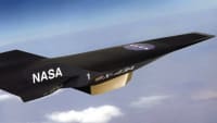
Aerospace & Defense Tech Briefs
Unmanned Aerial Systems Electromagnetic Induction Sensor Development
Aerospace & Defense Tech Briefs
Controlling Heat Spikes in Electric Aircraft at Takeoff
Aerospace & Defense Tech Briefs
AI-Trained Vehicles Can Adjust to Extreme Turbulence on the Fly

Aerospace INSIDER
4D Composite Printing Can Improve Drone Wings
Aerospace & Defense Tech Briefs
Advancing Metrology at Mach Speed
Tech Briefs
System Helps Drones Detect and Avoid Power Lines
Aerospace & Defense Tech Briefs
Investigation of Flight Dynamics and Controls for a Solar-Tracker-Mounted UAV
Aerospace & Defense Tech Briefs
Surviving the Challenge of Thermal Design in Aerospace Electronics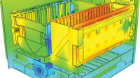
Aerospace & Defense Tech Briefs
Microturbine Propulsion for UAVs

Aerospace & Defense Tech Briefs
Unmanned Aerial System
Aerospace & Defense Tech Briefs
Autonomous Collaborative Platform

Aerospace & Defense Tech Briefs
PHASA-35 Stratospheric Flight
Top Stories
INSIDERDefense
![]() New Raytheon and Lockheed Martin Agreements Expand Missile Defense Production
New Raytheon and Lockheed Martin Agreements Expand Missile Defense Production
NewsAutomotive
![]() Ford Announces 48-Volt Architecture for Future Electric Truck
Ford Announces 48-Volt Architecture for Future Electric Truck
INSIDERManufacturing & Prototyping
![]() Active Strake System Cuts Cruise Drag, Boosts Flight Efficiency
Active Strake System Cuts Cruise Drag, Boosts Flight Efficiency
ArticlesTransportation
![]() Accelerating Down the Road to Autonomy
Accelerating Down the Road to Autonomy
INSIDERMaterials
![]() How Airbus is Using w-DED to 3D Print Larger Titanium Airplane Parts
How Airbus is Using w-DED to 3D Print Larger Titanium Airplane Parts
Road ReadyTransportation
Webcasts
Electronics & Computers
![]() Cooling a New Generation of Aerospace and Defense Embedded...
Cooling a New Generation of Aerospace and Defense Embedded...
Power
![]() Battery Abuse Testing: Pushing to Failure
Battery Abuse Testing: Pushing to Failure
Connectivity
![]() A FREE Two-Day Event Dedicated to Connected Mobility
A FREE Two-Day Event Dedicated to Connected Mobility
Automotive
![]() Quiet, Please: NVH Improvement Opportunities in the Early Design Cycle
Quiet, Please: NVH Improvement Opportunities in the Early Design Cycle
Transportation
![]() Advantages of Smart Power Distribution Unit Design for Automotive &...
Advantages of Smart Power Distribution Unit Design for Automotive &...
Aerospace
![]() Sesame Solar's Nanogrid Tech Promises Major Gains in Drone Endurance
Sesame Solar's Nanogrid Tech Promises Major Gains in Drone Endurance