


Improving Heavy-duty Engine Component Efficiencies
Cylinder deactivation can improve fuel economy by using a reduced number of cylinders that operate at higher loads and thermal efficiency, while other cylinders are turned off, when the engine operates at partial load conditions. A switching roller finger follower is one of the technologies that help make it work.
Cylinder deactivation (CDA) is an effective method to fine-tune engine displacement for maximum output and improve fuel economy by adjusting the number of active cylinders in combustion engines.
A switching roller finger follower (SRFF) is an economic solution for CDA that minimizes changes and preserves the overall width, height, or length of dual overhead cam (DOHC) engines. The SRFF is a mechanically actuated device that is hydraulically controlled using engine oil. A CDA SRFF provides the flexibility of either transferring or suppressing the camshaft movement to the valves influencing the engine performance and fuel economy by reducing the pumping losses.
The fuel economy benefits of CDA technology are estimated to be between 2-14%, depending on engine displacement and the number of cylinders that are deactivated. Typical fuel economy gains are 3-6% for six- and eight-cylinder engines. The improvements in fuel economy are possible by reducing the pumping losses when the engine operates in partial load conditions.
Researchers from Eaton recently studied the performance and durability of a CDA SRFF system that meets the reliability requirements for gasoline automotive engines. Of most importance, this technology — which provides a means for aftertreatment temperature management and fuel economy benefits — is scalable and can be applied to light-, medium-, and heavy-duty applications for gasoline, diesel, and natural gas engines.
Extensive tests were conducted to demonstrate the dynamic stability at high engine speeds and the system capacity of switching between high and low engine displacement within one camshaft revolution. The system durability was demonstrated with high and low engine speeds, various oil temperatures, mode switching, and abuse tests, meeting the end of life criteria in wear and function.
CDA system description
Several CDA systems exist today, each customized for a specific valvetrain architecture. The CDA design during the Eaton research project was configured for DOHC engines, in which a SRFF was used along with a single lobe camshaft for each of the deactivated valves.
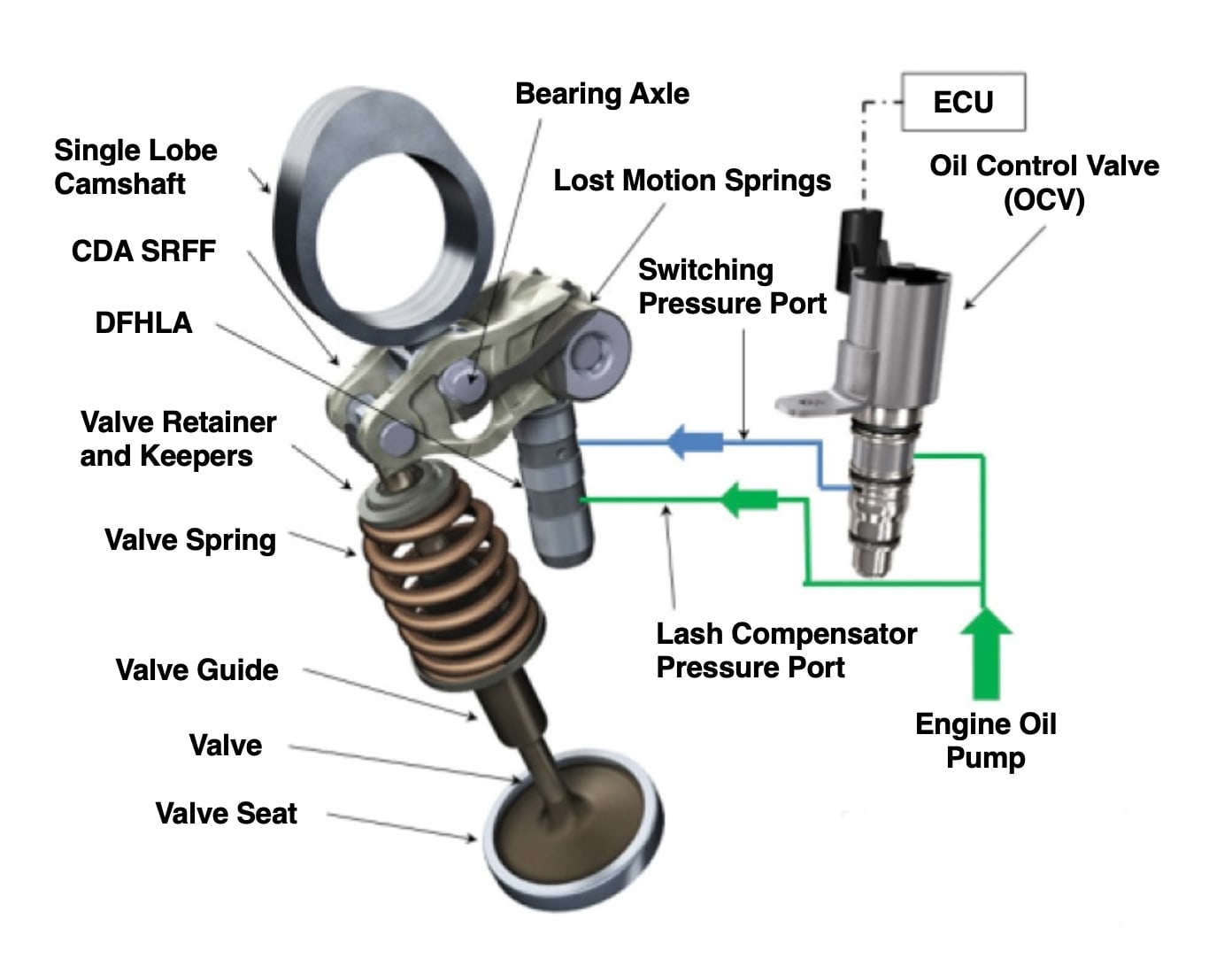
The system included two single lobe camshafts, four CDA SRFFs (two SRFFs for intake and two for exhaust valves), four dual-feed hydraulic lash adjusters (DFHLAs), one oil control valve (OCV), and four sets of the valve subsystem that include valve retainers, keepers, valve springs, valve guides, valves, and seats.
The camshaft for the CDA SRFF is very similar to camshafts used on traditional DOHC engines. The difference is that the camshaft ramps on the CDA system are longer than the ramps on the traditional systems in which typical valve components are used. The CDA SRFF includes an additional internal lash due to the switching mechanism that is not present on a traditional RFF that does not have a switching function. The camshaft ramps used on the CDA SRFF described here are longer to absorb a larger lash prior to the valve lift event. The CDA system does not require changes for any component of the valve subsystem.
The DFHLA is a specifically designed hydraulic lash adjuster (HLA) for SRFF systems that retains the functionality of lash compensation with the added function of providing a hydraulic conduit between the OCV and the SRFF. Engine oil is plumbed to the lash compensation port of the DFHLA. The DFHLA upper port is connected to the OCV through the switching pressure port. The OCV is an electronically controlled on/off valve that receives input from the engine control unit (ECU).
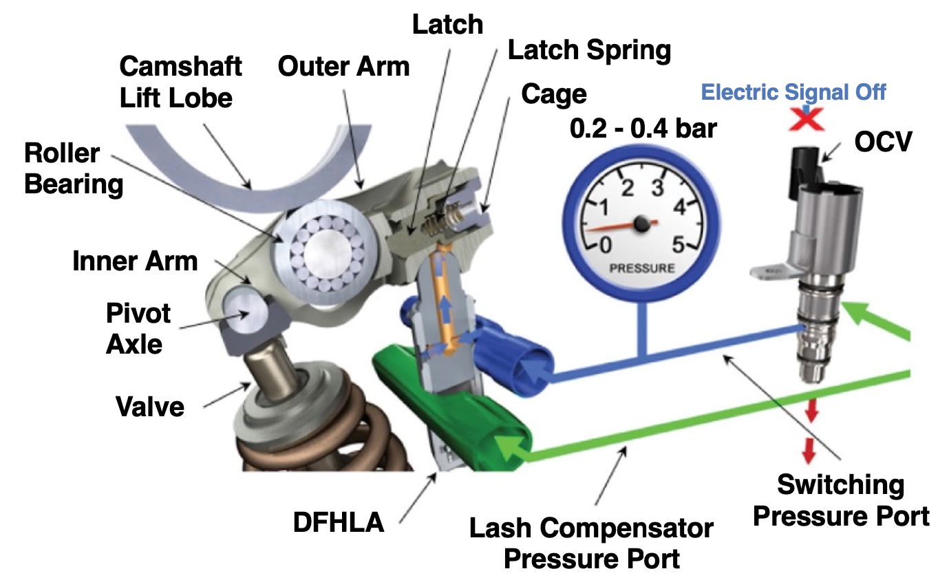
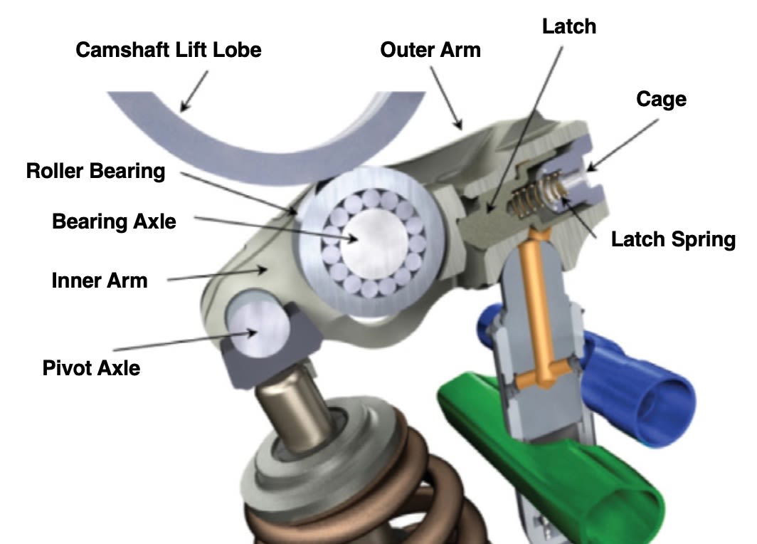
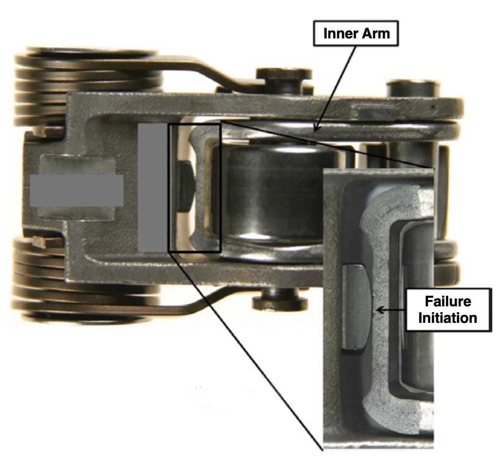
In the SRFF system, an inner arm resides inside an outer arm, and the two arms are connected at one end with a pivot axle, which is a permanent cylindrical joint. The latching mechanism is located opposite to the pivot axle of the SRFF and acts as the second connection for the inner arm. This connection can be turned on or off by moving the latch.
The latching mechanism consists of a latch, a latch spring that forces the latch to engage the inner arm, and a cage that is permanently connected with the outer arm. A roller bearing is connected to the inner arm via a bearing axle. A pair of lost-motion springs are connected to the outer arm at one end and the bearing axle on the other end, providing a permanent contact between the roller bearing and the camshaft.

The CDA system provides two operating modes. Standard lift mode is available at any engine speed and operating temperature. The oil pressure in the switching port is regulated to 0.2-0.4 bar, gage pressure, resulting in the latch being extended, engaging the inner arm when no electrical signal is sent to the OCV. The CDA (or no-lift) mode is available at speeds up to 3500 rpm and oil temperatures above 20°C. An electrical signal from the ECU triggers the OCV to open the switching pressure port to engine oil pressure that is above 2.0 bar, gage pressure at that moment. The increase in pressure moves the latch, disengaging the inner arm from the outer arm.
The engine switches to CDA mode in an operating range driven by the time available to switch between modes in one camshaft revolution. The factors accounted for in calculating the switching time available are the valve event duration, phasing between the intake and exhaust events, oil viscosity, oil pressure, and engine speed. Details about time available to switch within one camshaft revolution on VVA systems that use an SRFF are detailed in SAE International technical paper doi:10.4271/2012-01-1639.
Engine oil pressure is plumbed to the lash compensation port of the DFHLA and to the OCV. No electric signal is sent to the OCV. The OCV regulates the oil pressure in the switching pressure port to 0.2-0.4 bar with the purpose of keeping the switching port free of air for fast latch movement when mode switching is required. This pressure is below the required pressure to overcome the latch spring force and move the latch. The latch is engaged with the inner arm. The camshaft rotational motion is transferred to the valve through the inner arm that is connected with the outer arm. The valve motion follows the camshaft profile.
During the no-lift mode, an electric signal from the ECU energizes the solenoid inside the OCV, opening the switching pressure port to the engine oil pressure. A minimum of 2.0 bar oil pressure is needed to overcome the latch spring. The increase in pressure moves the latch to the retracted position, disengaging the inner arm. The inner arm and the outer arm remain connected at the pivot axle.
The absence of the secondary connection between the two components results in the camshaft rotational motion being transferred to the inner arm, which pivots around the axle and no camshaft motion is transferred to the valve, resulting in the valve remaining seated.
Engine life testing

Quality Function Deployment (QFD) methodology was used to understand the connection between the engine performance and durability requirements to SRFF targets for design, performance, durability, and reliability.
The CDA SRFF was divided into four primary subsystems: fatigue, wear-out, switching mechanism, and lost-motion. Each of the four subsystems was investigated to determine the appropriate life targets equivalent to 200,000 mi.
The 200,000 mi target was converted into a number of events that each subsystem would encounter over its lifetime. The number of valve events equivalent to 200,000 mi engine life is more than 300 million. This number was calculated based on a series of duty cycle scenarios.
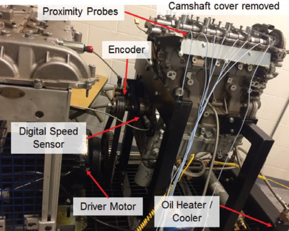
Valvetrain component wear was accelerated by increasing the engine speed to reduce the test time. A proprietary high-speed durability test cycle was utilized to establish valvetrain wear that is equivalent to 330 million valve events while only requiring a fraction of the test time.
An aggressive target of 15 switching events (lift to deactivation and back to lift again) per mile was established to ensure a robust design. The resulting target was 3 million switching events for the life of the engine. The lost-motion system life target was defined by a high-end user, which provided a conservative target.
The resultant life target was approximately 160 million lost-motion cycles. The SRFF must withstand several abuse events such as critical shifts (unintentional switches from lift mode to deactivation partway through a lift event) and high-speed excursions at speeds above the designed operating range over the course of 200,000 mi.
A target of 5000 critical shifts was set during the development of the CDA SRFF, a conservative approach considering the low frequency of critical shift occurrences. Excursions of five consecutive 10 second bursts were considered as the target for the over-speed test when in lift mode. The system was additionally tested to twice the rated lost-motion speed for a total of 10 million cycles to protect the engine in case of an SRFF being in CDA mode unintentionally for an extended time.
Valvetrain lash is a key end-of-life measureable for tests performed on the CDA SRFF. The camshaft profile is made for a max lash, which includes the SRFF lash as produced and the lash increase from wear. The acceptable SRFF lash target is set for a maximum increase of 20 micron over the course of 200,000 mi. The camshaft opening and closing ramps are designed for a set maximum lash value that must be absorbed prior to the lift event.
Lash was monitored at discrete inspection intervals throughout all tests to qualify the success of an ongoing test. Lash data acquired at each inspection interval are used to understand the trend of lash increase for the system, determine when the system stabilizes, and predict end of test lash increase.
The four subsystems of the SRFF were tested extensively to demonstrate reliability and durability to the life target of 200,000 mi. Demonstration of the SRFF reliability and durability was achieved by testing the subsystems of the SRFF beyond their respective single life targets.
Test results summary
The CDA SRFF was subjected to a series of tests encompassed by the four pillars of SRFF durability demonstration. First, the system performance was validated by successfully completing all tests in the performance verification pillar. Next, the subsystems of the SRFF were proven to function beyond the 200,000-mi life target. The SRFF proved to be robust to the abuse of extreme limit testing by successfully passing all tests without losing function. Finally, the SRFF showed it was capable of surviving five system durability lives, the equivalent of 1,000,000 mi of wear and tear.
The testing achievements were attained by testing greater than 500 SRFFs for a total cumulative test time of greater than 40,000 hours (320,000 component test hours).
The performance verification pillar is meant to ensure that the design of the SRFF meets certain design criteria to ensure consistent and acceptable performance in all engine operating conditions. The CDA SRFF demonstrated a fatigue suspension load more than twice the maximum dynamic load measured during valvetrain dynamics. Closing velocities of the SRFF maintained greater than a 40% margin to their limit for both intake and exhaust positions. Finally, the lost motion spring design was verified by demonstrating a minimum of a 10% margin to the pump-up condition in the worst-case condition with minimum specification lost motion springs.
The subsystem testing pillar was designed to ensure that the major subsystems of the SRFF function appropriately and will endure for the full duration of expected life. The switching mechanism managed to achieve a milestone of 15 million switching events compared to a life target of three million. After completing five lives on test, the SRFF maintained a 21% margin from the limit of lash wear. The lost-motion system proved it is robust to the extreme ends of the fatigue spectrum, achieving 200 million lost-motion cycles, which is 1.2 times greater than the expected worst case end-user.
The extreme limit test was designed to push the SRFF past intended functionality and ensure it was robust to conditions caused by failures of other systems within the engine. The SRFF demonstrated it could survive greater than 10,000 critical shifts, or two times the life target. The SRFF successfully passed all other abuse tests to which it was subjected.
Finally, the accelerated system aging pillar was meant to simulate a full 200,000-mi duty cycle on the valvetrain by maintaining an elevated engine speed and exercising all of the major SRFF subsystems. The CDA SRFF maintained a 51% margin to the maximum allowable lash increase after completing five lives of the system durability test, equivalent to 1,000,000 mi of wear and tear.
This article is based on SAE International technical paper doi:10.4271/2015-01-2816, by Andrei Radulescu, Leighton Roberts, and Eric Yankovic, Eaton.
More From SAE Media Group
Off-Highway Engineering
Scania Adapts On-Highway Diesel for New Off-Highway Engine Platform
Automotive Engineering
Extending a Wankel Future on Hydrogen Fuel
Off-Highway Engineering
Cummins’ X15 Is a Model of Design Efficiency
Off-Highway Engineering
Westport Awarded LNG Development Program
Off-Highway Engineering
Navistar Updates A26 Engine, Improves FE by 4%
Off-Highway Engineering
Cummins New X15 Engine Meets Upcoming Regs While Boosting Efficiency
Off-Highway Engineering
Mahle, Liebherr Develop Active Pre-Chamber for Hydrogen ICE
Automotive Engineering
An Exhaust Symphony in the Key of C8
Tech Briefs INSIDER
Replacing Camshafts with Valves Paves Way for Cheaper, Greener Engines
Off-Highway Engineering
Isuzu Simplifies Fuel Changeovers
Aerospace & Defense Tech Briefs
X Marks the Spot
Automotive Engineering
Engine Researchers: 50% Gasoline-Engine Efficiency in Sight
Off-Highway Engineering
Caterpillar Unveils New C13D Off-Highway Engine Platform
Off-Highway Engineering
Electric Actuators Can Benefit Heavy-Duty Diesels
Off-Highway Engineering
Cummins, Tula Test ‘Dynamic’ Cylinder Deactivation for Diesels
Automotive Engineering
Injecting a Sense of Urgency to Clean up Diesels
Off-Highway Engineering
Tailoring Fuel Injection to Control NOx
Off-Highway Engineering
Bigger Processors, Smaller Engines
Automotive Engineering
Extending the ICE Age: Hyundai Optimizing Engines and Fuels
Automotive Engineering
How Higher-Quality Gasoline Keeps Modern Engines Clean and Efficient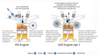
Off-Highway Engineering
Cummins Cylinder Deactivation Saves on Fuel and Emissions
Automotive Engineering
Stanadyne Pumps up the Volume
Automotive Engineering
German Spark-Ignited Compression-Ignition Research Paralleling Mazda’s SPCCI
Off-Highway Engineering
Komatsu Logs a New Timber Machine
Automotive Engineering
Optimizing Hybrids for Cost and Efficiency
Off-Highway Engineering
Combustion Engines Carry on in Construction
Off-Highway Engineering
Could This Infinitely Variable Compression Mechanism Be the Next Piston Engine Game-Changer?
Off-Highway Engineering
Kohler Extends Its Hand in Off-Highway Diesels
Automotive Engineering
Ford’s 1.0-L Triple Will Add Cylinder Deactivation in 2018
Automotive Engineering
Controlling Engines with Virtual Sensors
Top Stories
INSIDERManufacturing & Prototyping
![]() How Airbus is Using w-DED to 3D Print Larger Titanium Airplane Parts
How Airbus is Using w-DED to 3D Print Larger Titanium Airplane Parts
INSIDERManned Systems
![]() FAA to Replace Aging Network of Ground-Based Radars
FAA to Replace Aging Network of Ground-Based Radars
NewsTransportation
![]() CES 2026: Bosch is Ready to Bring AI to Your (Likely ICE-powered) Vehicle
CES 2026: Bosch is Ready to Bring AI to Your (Likely ICE-powered) Vehicle
NewsSoftware
![]() Accelerating Down the Road to Autonomy
Accelerating Down the Road to Autonomy
EditorialDesign
![]() DarkSky One Wants to Make the World a Darker Place
DarkSky One Wants to Make the World a Darker Place
INSIDERMaterials
![]() Can This Self-Healing Composite Make Airplane and Spacecraft Components Last...
Can This Self-Healing Composite Make Airplane and Spacecraft Components Last...
Webcasts
Defense
![]() How Sift's Unified Observability Platform Accelerates Drone Innovation
How Sift's Unified Observability Platform Accelerates Drone Innovation
Automotive
![]() E/E Architecture Redefined: Building Smarter, Safer, and Scalable...
E/E Architecture Redefined: Building Smarter, Safer, and Scalable...
Power
![]() Hydrogen Engines Are Heating Up for Heavy Duty
Hydrogen Engines Are Heating Up for Heavy Duty
Electronics & Computers
![]() Advantages of Smart Power Distribution Unit Design for Automotive...
Advantages of Smart Power Distribution Unit Design for Automotive...
Unmanned Systems
![]() Quiet, Please: NVH Improvement Opportunities in the Early Design...
Quiet, Please: NVH Improvement Opportunities in the Early Design...