


Monitoring and Charging System for a High-Power Battery
Cell potentials and temperatures are kept within safe ranges.
Figure 1 is a simplified block diagram showing (1) a high-power rechargeable battery comprising multiple series-connected modules, each module containing multiple series-connected rechargeable cells, and (2) a system for monitoring battery voltages and controlling the charging of the battery. To ensure safe, reliable operation of the battery, it is imperative to ensure that the potentials and temperatures of all the cells remain within prescribed limits. Accordingly, the system monitors the potential of each cell, the overall potential of each module, and the temperature of each cell. Because overcharging can damage a cell, if the potential of any cell exceeds a predetermined maximum allowable level, the system interrupts the charging process and starts another process, called “equalization,” in which the affected cell is partially discharged through a resistor until its potential reaches a prescribed safe lower level. If the temperature of any cell or module exceeds a predetermined maximum allowable value, or if a fault is detected, the system stops the charging process.

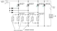
Associated with each module is a battery-control board. For measurement of the module potential, measurement of cell potentials, and equalization, all the cell terminals in the module are connected to voltage-measuring circuits and equalization-resistor-switching circuits on the battery-control board. The voltage-measuring circuit for each cell includes a differential amplifier, the output of which is digitized and fed to an on-board processor. The equalization resistor for each cell is switched into or out of contact with the cell terminals by a relay driven in response to a command from the on-board processor. The temperatures of the cells, of the module as a whole, and of the battery-control board are measured by sensors (e.g., thermistors or thermocouples), the outputs of which are also digitized and sent to the on-board processor.
The operation of the system as a whole and the operations of the battery-control boards are coordinated by a control computer. The processors on the battery-control boards communicate with the control computer via a network than can be of any wired or wireless type commonly used for communication among computers.
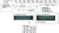
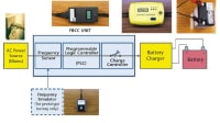
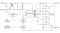
The system includes a charging subsystem that includes a fixed-output power supply for the control circuitry and an adjustable-output power supply for charging the battery (see Figure 2). Like the battery-control boards, the adjustable-output power supply communicates with the control computer via the network. The fixed-output power supply is used to energize a relay that controls the main power switch between the battery and the adjustable-output power supply. On each battery-control board, there is a relay, denoted a board relay, that opens a switch when equalization is needed, a cell temperature exceeds a preset limit, or a fault is detected. The board relay switches are connected in series with the main power relay, so that if any condition necessitating interruption or stoppage of charging is encountered in any cell in any module, the main power is turned off.

Multiple layers of redundant fault sensing and control are designed into the system. During charging, the control computer must be in constant communication with the battery-control boards and the adjustable-output power supply, and the processor on each battery-control board samples cell potentials and temperatures and compares them with the corresponding preset limits at a repetition rate of the order of several times per second. The control computer commands the adjustable-output power supply to zero-output potential when it receives, from any battery-control board, a cell-potential or a temperature reading out of allowable range. The control computer also disables the adjustable-output power supply if it loses communication with, or receives a fault message from, any battery-control board. The control computer can be made to display a graphical user interface showing cell potentials, module potentials, and module temperatures, and battery-control-board temperatures. The graphical user interface can be configured to function as a means for a user to exert control over charging and equalization.
This work was done by Daniel P. Thivierge of the Naval Undersea Warfare Center for the Naval Research Laboratory.
NRL-0024
This Brief includes a Technical Support Package (TSP).
Monitoring and Charging System for a High-Power Battery
(reference NRL-0024) is currently available for download from the TSP library.
Don't have an account?
More From SAE Media Group
Battery Technology
Charge Control Methods for Supercapacitors
Battery Technology
Active Battery Cell Balancing
Tech Briefs
Supercapacitors for Wearable Devices
Aerospace & Defense Tech Briefs
Optimizing IoMT Device Battery Life With Emulation and Profiling Software
Sensor Technology
Near-Zero-Power Temperature Sensor
Embedded Technology
Understanding the Unique Requirements of Portable Data Acquisition Systems
Sensor Technology
Energy Harvesting Can Enable 1 Trillion Battery-Free Sensors in the IoT
Automotive Engineering
Clarios to Build Supercapacitor Plant in U.S.
Medical Design Briefs
Flexible Screen-Printed Rechargeable Battery
Sensor Technology
Smart Batteries Include Force and Pressure Sensing
Battery Technology
Stretchable Micro-Supercapacitors Self-Power Wearable Devices
Aerospace & Defense Tech Briefs
Fuzzy System for Fault Diagnostics in Power Electronics-Based Brake-by-Wire System
Aerospace & Defense Tech Briefs
Analysis of Voltage and Current Signal Processing in a Li-ion Battery Management System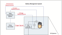


Medical Design Briefs
The Challenges of Handheld and Wearable Medical Device Batteries

Tech Briefs
Product of the Month


Tech Briefs
Low-Inductance DC Power Bus


Overview
The document pertains to a patent application from the Naval Undersea Warfare Center, identified by Attorney Docket No. 98638. It focuses on a Battery Monitoring and Charging System developed by inventor Daniel P. Thivierge. This invention is particularly relevant for high-power rechargeable batteries, which are increasingly used in applications such as electric vehicles and other advanced technologies.
The core of the invention lies in its advanced power management circuitry, designed to enhance the safety and efficiency of charging and discharging high-capacity batteries. Given the significant power levels involved, the document emphasizes the necessity for careful handling and close monitoring of these batteries during both charging and discharging processes. This is crucial to prevent potential hazards associated with battery malfunctions, such as overheating or failure, which can lead to safety risks.
The U.S. Government retains the rights to manufacture and use this invention without incurring any royalty fees, indicating its strategic importance for governmental applications. The document serves as a notice to potential licensees about the availability of this technology for commercial use, highlighting its potential benefits in various sectors, particularly in the growing field of electric vehicles.
The invention aims to address common challenges faced in battery management, such as ensuring optimal performance, extending battery life, and enhancing safety measures. By implementing this advanced monitoring and charging system, users can expect improved reliability and efficiency in battery operation, which is essential for the performance of electric vehicles and other high-demand applications.
Overall, the document outlines a significant technological advancement in battery management, with implications for both military and civilian applications. It invites interested parties to inquire further about licensing opportunities, suggesting a proactive approach to technology transfer and commercialization. The emphasis on safety and efficiency aligns with current trends in energy management and sustainability, making this invention a timely contribution to the field of battery technology.
For further inquiries or detailed information, interested parties are encouraged to contact the Patent Counsel as indicated in the document.
Top Stories
INSIDERDefense
![]() New Raytheon and Lockheed Martin Agreements Expand Missile Defense Production
New Raytheon and Lockheed Martin Agreements Expand Missile Defense Production
NewsAutomotive
![]() Ford Announces 48-Volt Architecture for Future Electric Truck
Ford Announces 48-Volt Architecture for Future Electric Truck
INSIDERManufacturing & Prototyping
![]() Active Strake System Cuts Cruise Drag, Boosts Flight Efficiency
Active Strake System Cuts Cruise Drag, Boosts Flight Efficiency
ArticlesTransportation
![]() Accelerating Down the Road to Autonomy
Accelerating Down the Road to Autonomy
INSIDERMaterials
![]() How Airbus is Using w-DED to 3D Print Larger Titanium Airplane Parts
How Airbus is Using w-DED to 3D Print Larger Titanium Airplane Parts
Road ReadyTransportation
Webcasts
Electronics & Computers
![]() Cooling a New Generation of Aerospace and Defense Embedded...
Cooling a New Generation of Aerospace and Defense Embedded...
Power
![]() Battery Abuse Testing: Pushing to Failure
Battery Abuse Testing: Pushing to Failure
Connectivity
![]() A FREE Two-Day Event Dedicated to Connected Mobility
A FREE Two-Day Event Dedicated to Connected Mobility
Automotive
![]() Quiet, Please: NVH Improvement Opportunities in the Early Design Cycle
Quiet, Please: NVH Improvement Opportunities in the Early Design Cycle
Transportation
![]() Advantages of Smart Power Distribution Unit Design for Automotive &...
Advantages of Smart Power Distribution Unit Design for Automotive &...
Aerospace
![]() Sesame Solar's Nanogrid Tech Promises Major Gains in Drone Endurance
Sesame Solar's Nanogrid Tech Promises Major Gains in Drone Endurance