


How to Specify and Select RF Filters

RF filters are critical components in aerospace and defense electronic systems. In high-frequency transmissions, they channel desired signals and reject unwanted signals, enabling reliable signal processing across the RF, microwave, and millimeter wave (mmWave) electromagnetic spectrum. In operating environments with many such signals, including from jammers trying to disrupt the operation of some systems, RF filters are employed in progressively higher frequencies. At the same time, systems engineers are requesting smaller filters that fit within drop-in surface mount technology (SMT) packages mounted within compact printed circuit board (PCB) assemblies.
Selecting a filter for an A&D application requires an understanding of available RF filter responses, physical formats, and technologies, with a good idea of necessary functional goals, such as separating channels or rejecting interference. The optimum filter for an aerospace and defense (A&D) system need not take up much space but should meet or exceed certain performance goals, such as passband insertion loss and stopband rejection. Commercial off-the-shelf (COTS) filters can sometimes provide the performance needed by A&D systems, but custom designs are often needed for top performance. Working closely with a filter designer and manufacturer can meet an A&D system’s RF filter requirements in a timely and reliable manner.
As with many other RF/microwave components tasked with signal processing in airborne or mobile systems, RF filters must often fulfill challenging size, weight, and power and cost (SWaP-C) requirements to fit in newer systems with strict miniaturization goals. The physical size of an RF filter will be dictated by several factors, including how much signal power must be processed and interconnecting components. For example, the highest-power RF filters typically have waveguide transmission-line construction with low insertion loss and high power-handing capability but with the tradeoff of the largest size of any RF filter topology. A smaller RF filter will suffice at lower signal power levels in a system with coaxial components. In small satellites and mobile systems, which require even less RF signal power, a filter housed in a surface mount technology (SMT) package may provide the channelization needed while also achieving demanding system miniaturization goals.
Including an RF/microwave filter within an A&D system enables selection and rejection of high-frequency signals for communications systems, radar systems, and systems that detect adversarial radar. High-frequency filters can be designed with various responses, such as bandpass filters, notch filters (also known as band-reject), low-pass filters, and highpass filters. Each allows a desired set of frequencies to pass while others are rejected.
Multiple filter responses are combined into diplexers, triplexers, and multiplexers to process multiple signal channels with minimal filtering hardware. A diplexer is a three-port RF component, making it possible to connect two transmitters at different frequencies to a single antenna. With an additional diplexer connected to the antenna and two receivers, a single antenna can transmit on one frequency channel and receive on a different frequency channel. A triplexer allows connecting three transmitters or receivers operating at different frequencies to the same antenna. A multiplexer is the means, within a reasonable channel count, to connect many communications transmitters and receivers to one or a limited number of antennas.
Diplexers, triplexers, and multiplexers sort transmitted and received signals in A&D electronic systems for communications, radar, spectrum monitoring, and surveillance. Within each component, RF filter circuitry in various forms separates and isolates the desired frequency channels from the many other EM signals in the operating environment. Several other RF filter-based components combine multiple filters to save physical size in a system, including the combination of RF filters with electromagnetic interference (EMI) filters. EMI filters help prevent EM energy from serving as noise within an electronic system, such as a communications radio. A combination RF/EMI filter eliminates the need for separate components, saving size and weight.
As newer A&D system designs seek increased functionality from smaller system sizes through smaller components, RF filters are among the components being designed into smaller volume packaging. Today’s RF filters must meet demanding SWaP requirements without sacrificing electrical performance. Larger systems may require the power-handling capabilities of waveguide RF filters or coaxial-packaged RF filters based on traditional microstrip, stripline, or coplanar waveguide (CPW) printed-circuit-board (PCB) structures. But at lower power levels and signal frequencies, drop-in or SMT filters often provide the RF filtering functions while supporting SWaP targets. Lower-power filters for processing 1W (+30 dBm) or less signal power include filters based on resonant materials such as surface-acoustic-wave (SAW) and bulk-acoustic-wave (BAW) materials.
SAW filters use various piezoelectric materials to convert input electrical energy to acoustic energy (where filtering is performed) and then back to electrical energy at the output utilizing interdigital transducers. They typically operate with 1W signal power or less and with RF signals as high as 2 GHz. BAW filters can cover the frequency range from about 1.5 to 6.0 GHz with slightly more signal power than SAW filters and fewer performance variations over wide operating temperature ranges. Both filter types can be housed in miniature drop-in and SMT packages for ease of mounting on PCBs. Passive RF filters are also fabricated on low-temperature-cofired-ceramic (LTCC) substrates, while active RF filters are based on semiconductor substrate materials such as gallium arsenide (GaAs).

When higher-frequency coverage is required, filters based on high-performance RF substrates enable processing signal frequencies from RF through millimeter wave with the aid of advanced manufacturing approaches including resist-defined photolithography and laser-formed microvia interconnections (Figure 1). Material selection is critical for RF filters to be used in A&D applications since RF/microwave filters for A&D systems in space must be designed to withstand the pyroshock or force of rocket takeoff during space system launch. An RF filter’s substrate material must be thermally efficient to provide consistent filtering performance while enduring the extreme temperature changes that space and defense systems encounter.
Filtering Specifications
Filling the RF filtering needs of A&D systems often starts with deciding whether a standard filter, such as a commercial-off-the-shelf (COTS) filter, can meet the electrical, environmental, and mechanical requirements of an application or system or if a custom RF filter will be required. The system’s spectral configuration will determine the type of filter response needed, such as bandpass to isolate a communications channel from noise or band-reject filter to block a jammer or interference signal.
A standard set of specifications characterizes RF/microwave filters for A&D systems: insertion loss, rejection, VSWR, power-handling capability, passive intermodulation (PIM), and quality factor (Q). For an RF bandpass filter, which is meant to preserve signals within the desired band and stop others at frequencies above and below the desired band, passband insertion loss refers to the attenuation of signal magnitude within the passband defined by the two frequencies at which the signal magnitude decreased by 50% or one-half power (by 3 dB).
For the bandwidth between those two -3-dB points or cutoff frequencies (Fc), the attenuation or insertion loss should be as low as possible. RF signal attenuation increases rapidly for the lower stopband of frequencies less than the low-frequency point of the passband and the upper stopband of frequencies greater than the high-frequency point of the passband. It is then defined as the filter’s rejection within its lower and upper stopbands, respectively, and should be as high as possible. A bandpass filter’s passband is often described as a percentage of the center frequency, such as 50 MHz being 5% of a 1-GHz center frequency.
Determining Tradeoffs in Specifications
Of course, many tradeoffs exist between different RF filter specifications, such as size and power-handling capability. The way an RF filter makes the transition from a passband to a stopband can be rapid or more gradual, typically determined by the classic RF filter response used in the design, such as Butterworth and Chebyshev filter responses. An RF filter that can transition from a low-loss passband to a high-rejection stopband in the shortest time or smallest frequency spectrum typically exhibits the highest amounts of passband (and stopband) ripple. Ripple refers to fluctuations in magnitude or signal power with frequency, impacting the phase response and group delay of an RF filter. An RF filter’s frequency response plot shows how its magnitude or signal power changes with frequency; a Bode plot also shows how the phase is affected in the passband.
Filter bandwidth is defined in several ways, especially with differences in response curves for various RF filter types. The Fc is often the quickest starting point when specifying a bandpass, band-reject, lowpass, or highpass filter because it identifies a spectral point at which signal loss changes from low to high. A lowpass filter typically has a passband beginning at DC or 0 Hz, but the actual frequency may also be a function of the filter’s packaging. In a high-pass filter, signals above Fc may transfer to the output with low loss but not reach mmWave frequencies because of the filter’s connectors and/or packaging.
Practical Solutions
As many A&D applications move higher in frequency in quest of available bandwidth at mmWave frequencies, filter designers are being asked for responses for systems operating at 30 GHz and higher, often from filters a fraction of the size of those working at RF and microwave frequencies. SWaP-C requirements for miniaturization guide system designers, and they expect the same or better performance levels at mmWaves as at lower frequencies but in a drop-in or SMT package. For filter designers, it is the opportunity to apply their creativity at higher frequencies to achieve performance, repeatability, and reliability. In some cases, such as RF filters for A&D systems that must comply with International Traffic in Arms Regulations (ITAR) requirements, those mmWave filters must also be manufactured in the United States. ITAR controls the manufacture, sale, and distribution of A&D components and services as defined by the U. S. Munitions List (USML).
For example, the recently introduced mmW-FH series of bandpass filters from Benchmark Lark Technology filter center frequencies from 5 to 30 GHz with available passbands of 2% to 5% (Figure 2). Housed in SMT packages less than 0.04 inches high, they are compatible with microstrip and stripline transmission-line technologies through mmWave frequencies.
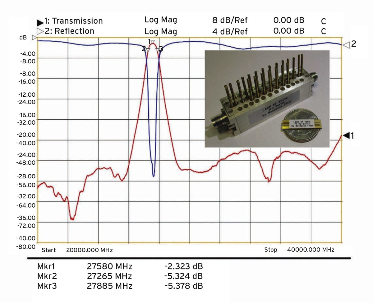
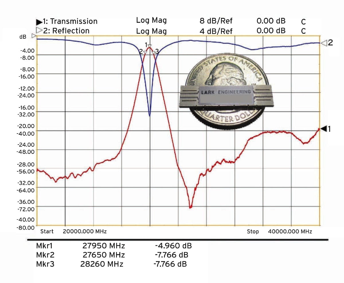
While custom components are available based on filtering requirements, a standard substrate-integrated-waveguide (SIW) 50-Ω bandpass model was developed for a center frequency of 27.95 GHz and 2.2% passband. It features more than 40 dB rejection outside the 610-MHz passband and 5-dB insertion loss at the center frequency and can fit within an SMT housing measuring 1.00 × 0.25 × 0.03 in. For the same size and bandwidth, the high-performance version of this series results in an insertion loss of better than 2.4 dB at 27.580 GHz (Figure 3). At even higher frequencies, the same company’s mmW-STL bandpass filters can be customized with center frequencies from 5 up to 40 GHz and passbands from 10% to 25%. A typical size for a nine-poles SMT mmW-STL bandpass filter at 39 GHz is in the range of 0.275 x 0.080 x 0.022 in.
Applications in A&D systems are moving to higher frequencies to meet increasing bandwidth requirements. RF, microwave, and mmWave filters are key components for minimizing interference and enabling the growing numbers of A&D systems even as they expand into higher frequency bands. Fortunately, for A&D system architects, these filters can be supplied in ever-smaller packages so that the benefits of RF filtering can be available without impacting SWaP-C.
This article was written by Francisco Hirata, Ph.D., R&D Engineer; Ani Herrera, Director of Engineering; Elizabeth Obiala, Ph.D, R&D Engineer; Art Aguayo, Channel Manager, Benchmark Lark Technology (Tempe, AZ). For more information, visit here .
More From SAE Media Group
Tech Briefs
Test Strategies to Track Hypersonic Threats
Aerospace & Defense Tech Briefs
Unmanned Ground Vehicle Communications Relays
Aerospace & Defense Tech Briefs
Air Force Technology Tracks “Sporadic E”
Aerospace & Defense Tech Briefs
Hardware Design of a High Dynamic Range Radio Frequency (RF) Harmonic Measurement System
Aerospace & Defense Tech Briefs
Solid-State Microwave Power Module
Aerospace & Defense Tech Briefs
Microwave Photonic Notch Filter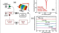
Aerospace & Defense Tech Briefs
An Integrated Framework for Complex Radar System Design
Tech Briefs
New Phase Shifter to Reduce Antenna Signal Loss
Aerospace & Defense Tech Briefs
RF FPGAs for Multi-Function Systems
Aerospace & Defense Tech Briefs
What Today’s Advances in Radar Technology Mean for Testing and Training
Aerospace & Defense Tech Briefs
Four RF Technology Trends You Need to Know for Satellite Communication Device Design
Aerospace & Defense Tech Briefs
Making Fully Digital Beamforming for Radar and Electronic Warfare Applications a Reality
Aerospace & Defense Tech Briefs
Key Measurements to Maintain Performance of Critical Electronic Systems on Military Aircraft and Warships
Aerospace & Defense Tech Briefs
Bringing RF into the Embedded World: It's Time
Aerospace & Defense Tech Briefs
Radio Relays Improve Wireless Products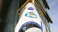
Aerospace & Defense Tech Briefs
RF Technology Helps Connect Avionics Systems
Tech Briefs
Radio Signals Image Hidden and Speeding Objects
Aerospace & Defense Tech Briefs
Software-Defined Analog Filters: A Paradigm Shift in Radio Filter Performance and Capability
Aerospace & Defense Tech Briefs
Replacing Multiple RF Receivers with Just One Using Channelization
Aerospace & Defense Tech Briefs
New Pulse Analysis Techniques for Radar and EW
Aerospace & Defense Tech Briefs
Making AESA Radar More Flexible
Aerospace & Defense Tech Briefs
Next-Generation Phased Radar Systems Lead to Hardware Improvements
Aerospace & Defense Tech Briefs
Tracking WiFi Signals to Passively See Through Walls
Aerospace & Defense Tech Briefs
90° Hybrid Coupled Power Amplifier – Pros and Cons
Aerospace & Defense Tech Briefs
What is Pulse Shaping?
Aerospace & Defense Tech Briefs
Digital Radar Warning Receiver

Aerospace & Defense Tech Briefs
New RF Strategies for Software Radio
Aerospace & Defense Tech Briefs
Enhance EMC Testing with Digital IF
Top Stories
NewsRF & Microwave Electronics
![]() Microvision Aquires Luminar, Plans Relationship Restoration, Multi-industry Push
Microvision Aquires Luminar, Plans Relationship Restoration, Multi-industry Push
INSIDERAerospace
![]() A Next Generation Helmet System for Navy Pilots
A Next Generation Helmet System for Navy Pilots
INSIDERDesign
![]() New Raytheon and Lockheed Martin Agreements Expand Missile Defense Production
New Raytheon and Lockheed Martin Agreements Expand Missile Defense Production
INSIDERMaterials
![]() How Airbus is Using w-DED to 3D Print Larger Titanium Airplane Parts
How Airbus is Using w-DED to 3D Print Larger Titanium Airplane Parts
NewsPower
![]() Ford Announces 48-Volt Architecture for Future Electric Truck
Ford Announces 48-Volt Architecture for Future Electric Truck
ArticlesAR/AI
Webcasts
Electronics & Computers
![]() Cooling a New Generation of Aerospace and Defense Embedded...
Cooling a New Generation of Aerospace and Defense Embedded...
Power
![]() Battery Abuse Testing: Pushing to Failure
Battery Abuse Testing: Pushing to Failure
Communications
![]() A FREE Two-Day Event Dedicated to Connected Mobility
A FREE Two-Day Event Dedicated to Connected Mobility
Unmanned Systems
![]() Quiet, Please: NVH Improvement Opportunities in the Early Design Cycle
Quiet, Please: NVH Improvement Opportunities in the Early Design Cycle
Transportation
![]() Advantages of Smart Power Distribution Unit Design for Automotive &...
Advantages of Smart Power Distribution Unit Design for Automotive &...
Energy
![]() Sesame Solar's Nanogrid Tech Promises Major Gains in Drone Endurance
Sesame Solar's Nanogrid Tech Promises Major Gains in Drone Endurance