


Low-Power Circuit for an Electromagnetic Warning System Sensor
This circuit was test-built to be used as a metric to evaluate an isotope battery.
Low-power sensors are important to the Army for monitoring infrastructure of the lifecycle of an operation. Isotope batteries can power and operate compact, low-power sensors for decades. A lowpower circuit has been developed to generate a repetitive radio frequency (RF) impulse, which will be used to indicate that a sensor has detected a target. This sensor circuit has been modeled and built to evaluate several isotope batteries in preparation. A parametric study of components in the circuit has been performed to minimize power consumption as a function of repetition rate and pulse width of the light-emitting diode indicator or RF impulse output.
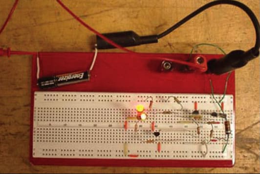
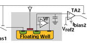
The circuit used in this sensor simulator is a discrete element replacement for the circuit found in the LM3909 LED flasher oscillator. The application for this circuit is as follows: If a sensor/detector attached to the circuit goes positive, the flasher will be initiated. The LED in this circuit could just as easily be replaced by a small, teardropmonopole antenna. The resulting mW power levels of radio frequency (RF) radiation will identify activity, and would be a good sensor circuit for a wireless array.
The circuit was constructed on a breadboard. Measurements were performed to identify voltage and current across significant components in the circuit that were involved in this parameter study. The components of interest included the diode resistor R3, the repetition rate resistors (R10 and R5), and the capacitor C1. After recording voltage and current, measurements were made to identify how much power and energy are needed to turn on and sustain the circuit for longer than merely a few cycles. By understanding the effects of varying these components, an understanding of the tradespace can be developed for the application of this sensor/circuit.
This work was done by John Russo, James Brent, and Marc Litz of the Army Research Laboratory. For more information, download the Technical Support Package (free white paper) at www.defensetechbriefs.com/tsp under the Electronics/Computers category. ARL-0088
This Brief includes a Technical Support Package (TSP).
Low-Power Circuit for an Electromagnetic Warning System Sensor
(reference ARL-0088) is currently available for download from the TSP library.
Don't have an account?
More From SAE Media Group
Sensor Technology
Near-Zero-Power Temperature Sensor
Tech Briefs
Rad-Hard CMOS Crystal Oscillator
Tech Briefs
High-Reliability Radio Frequency MEMS Switch


Aerospace & Defense Tech Briefs
Energy-Filtered Tunnel Transistor: A New Device Concept Toward Extremely Low Energy Consumption Electronics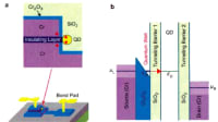
Aerospace & Defense Tech Briefs
Life Tests of a Microwave MEMS Capacitive Switch
Aerospace & Defense Tech Briefs
Improved Magnetic Sensor Based on Giant Magneto-Impedance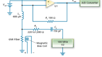
Tech Briefs
Vibration-Powered Lowpass Filter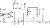
Sensor Technology
Smart Batteries Include Force and Pressure Sensing

Tech Briefs
164-GHz MMIC HEMT Frequency Doubler
Tech Briefs
Ultrahigh-Energy-Density Capacitor
Battery Technology
Stretchable Micro-Supercapacitors Self-Power Wearable Devices


Electronics & Sensors INSIDER
A New Magnetic Transistor for More Energy-Efficient Electronics
Battery Technology
Charge Control Methods for Supercapacitors

Tech Briefs
Small X-Band Oscillator Antennas


Tech Briefs
Silicon Carbide High-Voltage Switch
Tech Briefs
Supercapacitors for Wearable Devices
Tech Briefs
New on the Market
Overview
The document titled "Low Power Circuit for EM Warning System Sensor" is an interim report authored by John Russo, James Brent, and Marc Litz, published by the U.S. Army Research Laboratory in September 2009. The report focuses on the development of a low-power circuit designed for electromagnetic (EM) warning system sensors, which are crucial for monitoring infrastructure throughout their operational lifecycle.
The report begins with a background section that outlines the importance of low-power sensors in military applications, particularly for long-term monitoring. It highlights the potential of isotope batteries to power compact sensors for extended periods, thereby enhancing operational efficiency and reliability.
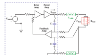
The core of the report details the circuit design and its components, including transistors and light-emitting diodes (LEDs). The authors provide a comprehensive circuit description, explaining the logic and functionality of the system. A significant aspect of the report is the PSpice modeling section, where the authors conduct a parametric variation of components to analyze their impact on circuit performance. This includes examining the effects of capacitance, resistances, and diode resistors on power dissipation and overall circuit efficiency.
Experimental results are presented, comparing the modeled circuit with actual measurements. The findings indicate that the developed circuit successfully generates a repetitive radio frequency (RF) impulse, which serves as an indicator when a sensor detects a target. The report emphasizes the importance of minimizing power consumption while maintaining effective performance, detailing how the repetition rate and pulse width of the RF output can be optimized.
In the conclusions section, the authors summarize the key outcomes of their research, noting that the simulation and measurement results align well, confirming the circuit's effectiveness. The report also includes a list of symbols, abbreviations, and acronyms used throughout the document, as well as a distribution list for the report.
Overall, this document serves as a valuable resource for understanding the advancements in low-power sensor technology, particularly in military applications, and provides insights into the design and modeling of circuits that can operate efficiently over extended periods. The findings contribute to the ongoing efforts to enhance sensor capabilities in various operational contexts.
Top Stories
INSIDERDefense
![]() New Raytheon and Lockheed Martin Agreements Expand Missile Defense Production
New Raytheon and Lockheed Martin Agreements Expand Missile Defense Production
NewsAutomotive
![]() Ford Announces 48-Volt Architecture for Future Electric Truck
Ford Announces 48-Volt Architecture for Future Electric Truck
INSIDERManufacturing & Prototyping
![]() Active Strake System Cuts Cruise Drag, Boosts Flight Efficiency
Active Strake System Cuts Cruise Drag, Boosts Flight Efficiency
ArticlesTransportation
![]() Accelerating Down the Road to Autonomy
Accelerating Down the Road to Autonomy
INSIDERMaterials
![]() How Airbus is Using w-DED to 3D Print Larger Titanium Airplane Parts
How Airbus is Using w-DED to 3D Print Larger Titanium Airplane Parts
Road ReadyTransportation
Webcasts
Electronics & Computers
![]() Cooling a New Generation of Aerospace and Defense Embedded...
Cooling a New Generation of Aerospace and Defense Embedded...
Power
![]() Battery Abuse Testing: Pushing to Failure
Battery Abuse Testing: Pushing to Failure
Connectivity
![]() A FREE Two-Day Event Dedicated to Connected Mobility
A FREE Two-Day Event Dedicated to Connected Mobility
Automotive
![]() Quiet, Please: NVH Improvement Opportunities in the Early Design Cycle
Quiet, Please: NVH Improvement Opportunities in the Early Design Cycle
Transportation
![]() Advantages of Smart Power Distribution Unit Design for Automotive &...
Advantages of Smart Power Distribution Unit Design for Automotive &...
Aerospace
![]() Sesame Solar's Nanogrid Tech Promises Major Gains in Drone Endurance
Sesame Solar's Nanogrid Tech Promises Major Gains in Drone Endurance