


Multiphysics Modeling and Simulation Enhances BESS Design
Battery energy storage systems (BESS) are designed for various applications, including maintaining stable power distribution. Engineers and researchers can use simulation software to study batteries at different scales, incorporating thermal management to maximize BESS performance and extend their operational life.

Electrical grids and data centers around the world use battery energy storage systems (BESS) as a power source, and the adoption of BESS is only continuing to grow. The BESS market hit a record in 2024, showing a 53 percent year-on-year global increase in BESS installations. 1 This rise in installations coincides with growing global electricity consumption. 2 One reason for this is that BESS are valuable in grid management programs, such as programs for power capacity management. BESS can be used to handle load fluctuations, enabling smooth adjustments of load increases or decreases and helping to maintain society’s electricity consumption habits.
Elevated electrical demands and greater reliance on BESS have heightened the need to produce high-performance, long-lasting BESS. In order to produce these optimal batteries and BESS, designers must analyze the thermal behavior in their designs and implement a thermal management system. Multiphysics modeling and simulation enables designers to study the thermal behavior in a BESS at the cell and pack levels and analyze effective thermal management strategies.
BESS Thermal Behavior and Management at Different Scales
Poor thermal management in a BESS directly impacts its performance and degradation, making it crucial that designers perform heat transfer studies of the system. While physical experiments remain an important piece of battery development, engineers can lean on modeling and simulation to easily perform thermal studies at different scales. By simulating the thermal behavior of batteries and virtually testing thermal management systems, engineers can develop BESS that better mitigate heat-related issues.
Let’s take a closer look at how modeling at the cell and pack scales can help battery designers analyze and optimize thermal management.
Thermal Behavior at the Cell Scale
At the cell level, battery models are developed for various cell formats and chemistries to meet specific design goals. Engineers can design and simulate battery cells, incorporating various components and exploring different load profiles to identify key variables that impact cell behavior and track performance indicators like voltage, state of charge (SOC), and internal resistance. Users can predict degradation and develop strategies to improve battery lifespan and performance by analyzing aging effects during cycling and storage. Battery cell performance and degradation are temperature dependent.
Higher temperatures can accelerate certain degradation mechanisms, while lower temperatures can trigger aging mechanisms such as plating. To understand these effects, battery models can be integrated with heat transfer analysis, creating an electrothermal model. Such a model helps designers assess the impact of temperature on cell performance and aging, detect hot spots, and evaluate the effectiveness of cooling strategies for managing thermal conditions. Rather than iterating with physical designs, conducting cell-level analysis through modeling and simulation provides a solid understanding before moving on to pack implementation.
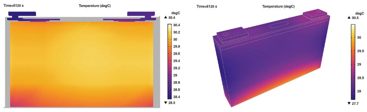
The modeling example shown in Figure 1 is of a prismatic lithium-ion battery cell, which is a battery type commonly used in BESS. This example demonstrates a full 3D prismatic battery equipped with two jelly rolls. The model includes a local thermal balance that considers heat sources from the irreversible activation losses and ohmic losses (Joule heating), as well as reversible losses due to reversible entropy changes.
Solving this model reveals that the temperature varies to a relatively small extent in this cell. The temperature increases during charge and discharge, and the maximum temperature is obtained inside the jelly roll, which is more or less in the middle of the cell. This investigation into a prismatic battery cell also shows the external temperature varying due to the high thermal conductivity of the metal parts relative to the low conductivity of the electrical insulators. The highest temperature is obtained at the bottom of the cell, where the jelly roll is in close contact with the battery can.
Thermal Management Analysis at the Pack Scale
At the pack scale, design engineers are able to assess how the larger system will operate. As with other battery applications, a BESS must cope with degradation and temperature regulation. While working at the pack level, designers can see if cells are degrading at different rates or heating more than neighboring cells.
With modeling and simulation, it is possible to create 3D pack geometries that include hundreds of cells arranged in various configurations. Designers can incorporate temperature effects and conduct full electrothermal analyses of models. With these analyses, they can see the voltage of each cell and how the temperature is distributed.
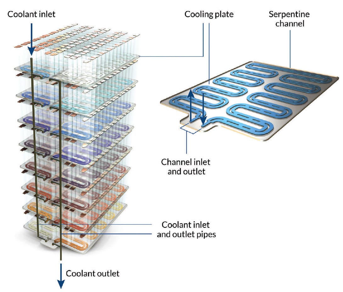
The example model shown in Figure 2 looks at the effects of liquid cooling for 56 cells. This model can incorporate capacity loss and be used to visualize the aging effects on the design and determine which design alteration best mitigates these effects.
BESS also include components that impact the overall thermal management. This includes cooling-related components and electrical wiring (e.g., feeders, current collectors, and busbars). Each aspect can be modeled individually and together as a system.
In the liquid-cooling example, the batteries are modeled using a predefined battery pack interface, which also accounts for the electric conductors that connect the batteries. The interface automatically calculates the heat generated due to electrochemical losses in the battery cells and Joule heating in the conductors.

To truly build out the prospective BESS design, engineers can include grilles, cooling channels, and coolant distribution pipes. They can conduct a conjugate heat transfer analysis that incorporates fluid flow dynamics (e.g., liquid coolant flowing through the cooling channels), which provides insights into temperature distribution and cooling efficiency. Figure 3 presents the temperature profile of the liquid-cooling system operating at a rate of 1 °C over a simulation period of 14,000 seconds. The results indicate that the temperature within the BESS varies by approximately 13 °C, with a maximum recorded value of 28 °C during the simulation.
Facilitating the Growth of BESS with Modeling and Simulation
BESS are capable of supporting energy-intensive applications, storing energy to stabilize the grid and providing backup power when needed. With the higher energy demand on these systems and the associated high temperatures, their optimization is key. Engineers can use modeling and simulation to virtually prototype designs they can be confident in while decreasing the time and cost required to test trial designs.
Here, we reviewed two modeling scales for BESS design and showed examples of lithium-ion batteries. Multiphysics modeling and simulation analysis can be extended to various cell formats, such as cylindrical and pouch cells, as well as alternative battery chemistries and BESS cooling methods.
This article was written by Niloofar Kamyab, COMSOL, Inc. (Burlington, MA). For more information, visit here .
References
- I. Hughes, “Global BESS deployments soared 53% in 2024,” Energy Storage News, Jan. 2025.
- Electricity 2025, IEA, license: CC BY 4.0, Paris, 2025.
More From SAE Media Group
Aerospace & Defense Tech Briefs
Improving Battery Design for eVTOL Aircraft With Simulation
Battery & Electrification Technology
Examining EV Battery Thermal Management
Battery & Electrification Technology
New Products
Battery & Electrification Technology
New Products
Battery & Electrification Technology
Powering Light Electric Vehicles

Battery & Electrification Technology
New Products
Tech Briefs
New Fluids Coming for EV Thermal Management
Battery & Electrification Technology
Driving EV Development with a Twin-Battery Approach
Tech Briefs
Is it Possible to Predict Car Battery Life?
Tech Briefs
Behold: The Oxygen-Ion Battery

Power Electronics INSIDER
World’s Strongest Battery Paves Way for Light, Energy-Efficient Vehicles

Battery & Electrification Technology
Breaking the Rules to Build a Better Battery
Battery & Electrification Technology
Oxygen-Ion Battery: A Solution for Large Energy Storage Systems

Battery & Electrification Technology
New Products
Battery & Electrification Technology
How Battery Simulation Is Taking High-Performance EV Development to New Heights
Battery & Electrification Technology
An Energy-Storing Concrete-Based Supercapacitor

Battery & Electrification Technology
Safe and Energy-Efficient Quasi-Solid Battery for Electric Vehicles and Devices
Battery & Electrification Technology
Refining Automotive Battery Management Systems with Lumped-Approach Thermal Modeling
Tech Briefs
A New, Low-Cost Aluminum-Sulfur Battery
Battery & Electrification Technology
Product Showcase

Tech Briefs
A Safer, More Efficient Lithium Metal Battery
Battery & Electrification Technology
New Products

Battery & Electrification Technology
Testing Times: Understanding the Impact of Climatic Conditions on EV Charging Times
Top Stories
INSIDERManufacturing & Prototyping
![]() How Airbus is Using w-DED to 3D Print Larger Titanium Airplane Parts
How Airbus is Using w-DED to 3D Print Larger Titanium Airplane Parts
NewsAutomotive
![]() Microvision Aquires Luminar, Plans Relationship Restoration, Multi-industry Push
Microvision Aquires Luminar, Plans Relationship Restoration, Multi-industry Push
INSIDERAerospace
![]() A Next Generation Helmet System for Navy Pilots
A Next Generation Helmet System for Navy Pilots
INSIDERDesign
![]() New Raytheon and Lockheed Martin Agreements Expand Missile Defense Production
New Raytheon and Lockheed Martin Agreements Expand Missile Defense Production
ArticlesAR/AI
![]() CES 2026: Bosch is Ready to Bring AI to Your (Likely ICE-powered) Vehicle
CES 2026: Bosch is Ready to Bring AI to Your (Likely ICE-powered) Vehicle
Road ReadyDesign
Webcasts
Semiconductors & ICs
![]() Advantages of Smart Power Distribution Unit Design for Automotive...
Advantages of Smart Power Distribution Unit Design for Automotive...
Unmanned Systems
![]() Quiet, Please: NVH Improvement Opportunities in the Early Design...
Quiet, Please: NVH Improvement Opportunities in the Early Design...
Electronics & Computers
![]() Cooling a New Generation of Aerospace and Defense Embedded...
Cooling a New Generation of Aerospace and Defense Embedded...
Power
![]() Battery Abuse Testing: Pushing to Failure
Battery Abuse Testing: Pushing to Failure
AR/AI
![]() A FREE Two-Day Event Dedicated to Connected Mobility
A FREE Two-Day Event Dedicated to Connected Mobility