


Fabricating Biologically Inspired Artificial Haircell Sensors
These sensors would control the flight of micro air vehicles.
As electronics packaging and equipment have decreased in size and weight, so have the potential dimensions of unmanned aircraft. Specifically, a classification of micro air vehicles (MAVs) has emerged that limits the scale of the aircraft to approximately 6" (15 cm). A project is underway aimed at developing artificial haircell flow sensors following biological inspiration of insect flow sensors, and demonstrate the potential of these sensors for controlling the flight of MAVs.
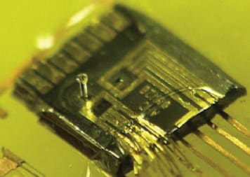
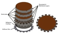
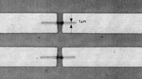
Individual silicon sensors are then packaged to provide robustness and electrical access. The cantilever beam is 200 μm long, 20 μm wide, and 2 μm thick. The hair is typically 100-750 μm tall. The height of the hair is controlled by the thickness of the deposited layer. The resonant frequency of the cantilever is approximately 1-5 kHz, depending on the dimensions of the cantilever and the hair. A high-yield process for fabricating the sensors has been invented. The sensor is fabricated using a silicon-on-insulator wafer (SOI), with the top silicon layer’s thickness being the thickness of the silicon cantilever.
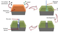
First, the SOI wafer is selectively doped to form piezoresistors for strain sensing. Secondly, the wafer is photolithographically defined using photoresist and etched with plasma etching until the underlying silicon oxide insulator layer is exposed. The backside of the wafer is then patterned and etched using deep reactive ion etching method to define the backside cavity. A front side deposition of photodefinable epoxy is carried out, followed by photo exposure to define the hairs. Development of photosensitive polymer is not performed immediately. The oxide is removed by backside etching. After this step, the wafer is diced into chips and then the photo definable epoxy is developed.
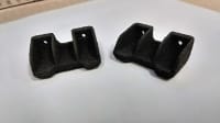
The sensors are packaged and placed on aerodynamic airfoils with flush mounting. Towards this end, the airfoil structures are first machined and then grooves of controlled dimensions are produced, which match those of the haircell chip. The sensorized airfoil is then placed in a flow tunnel. The wing is attached to a six-degrees-of-freedom balance that measures the mo ment and force applied to the wing.
This work was done by Chang Liu of the University of Illinois at Urbana-Champaign for the Air Force Research Laboratory. AFRL-0124
This Brief includes a Technical Support Package (TSP).
Fabricating Biologically Inspired Artificial Haircell Sensors
(reference AFRL-0124) is currently available for download from the TSP library.
Don't have an account?
More From SAE Media Group
Tech Briefs
SiC-Based Microstructures for Sensors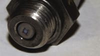

Medical Manufacturing and Machining INSIDER
New Electronics Manufacturing Process Could Lead to Breakthroughs in Prosthetics


Tech Briefs
5 Ws of Electronic Stickers
Automotive Engineering
Moving Targets: How Improvements to SiC, GaN Power Electronics Will Redefine EV
Tech Briefs
Artificial Hair Cells for Sensing Flows
Tech Briefs
Product of the Month
Aerospace & Defense Tech Briefs
‘Nanostitches’ Enable Lighter and Tougher Composite Materials
Aerospace & Defense Tech Briefs
Patterning of Polycrystalline Bi2Te3 Thin Films on Silicon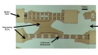
Motion Design INSIDER
New Transfer Process Moves 2D Materials from Growth Substrate to Device Substrate
Aerospace & Defense Tech Briefs
Fiber-Reinforced Thermoplastic Composites
Tech Briefs
New Ultra-Strong Material for Microchip Sensors
Aerospace Manufacturing and Machining
Why Heat Exchanger Manufacturers Need to Rethink Design and Fabrication

Photonics Tech Briefs
Fabricating Small Apertures in Silicon-on-Insulator Wafers
Tech Briefs
New Printing Process Advances 3D Capabilities
Tech Briefs
Printing Microchip Patterns on Curvy Surfaces
Tech Briefs
Automated Tow/Tape Placement System
Overview
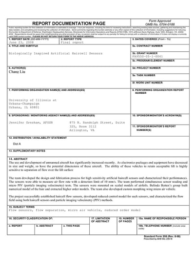
The document is a final report on the development of biologically inspired artificial haircell sensors, authored by Chang Liu from the University of Illinois at Urbana-Champaign. It discusses the increasing significance of unmanned aircraft, particularly micro-air-vehicles (MAVs), which are limited to approximately 6 inches (15 cm) in size and operate at low Reynolds numbers (Re < 10^6). The report emphasizes the critical role of flow separation over lift surfaces in maintaining acceptable lift for these vehicles.
The research focuses on understanding flow events leading to separation, which is vital for improving the performance of unmanned aircraft. It identifies two main types of flow events: small-scale disturbances associated with leading edge separation and larger structures formed during completely separated flow at high angles of attack. The study references the work of McCullough and Gault, who categorized three main types of airfoil stall: trailing edge, leading edge, and thin airfoil stall. The report highlights the importance of recognizing the time-dependent nature of separation conditions, which could lead to new control algorithms for enhanced aircraft performance.
The team developed high-sensitivity artificial haircell sensors capable of measuring airflow rates with a detection limit of 10 mm/s. These sensors were tested alongside micro particle imaging velocimetry (PIV) methods on scaled models of airfoils. The report details the design and fabrication process of these sensors, their performance characterization, and the successful establishment of haircell flow sensors. The sensors are intended for applications in monitoring airflow on large aircraft wings and in medical instruments.
The document also discusses the potential for these sensors to improve flow control techniques by providing detailed insights into the behavior of structures in low Reynolds number flow over airfoils. Understanding the periodic nature of flow structures and their associated frequencies can lead to improved methods for delaying or counteracting flow separation effects.
In summary, the report presents significant advancements in sensor technology for unmanned aircraft, emphasizing the importance of flow management in enhancing lift and overall performance. The findings contribute to the broader field of aerodynamics and control systems for autonomous vehicles.
Top Stories
NewsSensors/Data Acquisition
![]() Microvision Aquires Luminar, Plans Relationship Restoration, Multi-industry Push
Microvision Aquires Luminar, Plans Relationship Restoration, Multi-industry Push
INSIDERRF & Microwave Electronics
![]() A Next Generation Helmet System for Navy Pilots
A Next Generation Helmet System for Navy Pilots
INSIDERWeapons Systems
![]() New Raytheon and Lockheed Martin Agreements Expand Missile Defense Production
New Raytheon and Lockheed Martin Agreements Expand Missile Defense Production
NewsAutomotive
![]() Ford Announces 48-Volt Architecture for Future Electric Truck
Ford Announces 48-Volt Architecture for Future Electric Truck
INSIDERAerospace
![]() Active Strake System Cuts Cruise Drag, Boosts Flight Efficiency
Active Strake System Cuts Cruise Drag, Boosts Flight Efficiency
ArticlesTransportation
Webcasts
Aerospace
![]() Cooling a New Generation of Aerospace and Defense Embedded...
Cooling a New Generation of Aerospace and Defense Embedded...
Energy
![]() Battery Abuse Testing: Pushing to Failure
Battery Abuse Testing: Pushing to Failure
Power
![]() A FREE Two-Day Event Dedicated to Connected Mobility
A FREE Two-Day Event Dedicated to Connected Mobility
Automotive
![]() Quiet, Please: NVH Improvement Opportunities in the Early Design Cycle
Quiet, Please: NVH Improvement Opportunities in the Early Design Cycle
Electronics & Computers
![]() Advantages of Smart Power Distribution Unit Design for Automotive &...
Advantages of Smart Power Distribution Unit Design for Automotive &...
Unmanned Systems
![]() Sesame Solar's Nanogrid Tech Promises Major Gains in Drone Endurance
Sesame Solar's Nanogrid Tech Promises Major Gains in Drone Endurance