


OBD Evolves for ICE and Zero-emission Propulsion Systems

On-board diagnostics (OBD) systems support the protection of the environment against harmful pollutants such as carbon monoxide (CO), nitrogen oxide (NOx), hydrocarbons (HC) and particulate matters (PM) emitted by combustion engines. OBD regulations require passenger cars and light-, medium- and heavy-duty trucks to support a minimum set of diagnostic information to external (off-board) “generic” test equipment.
For the purpose of communication, both the test equipment and the vehicle must support the same communication protocol stack. The communication protocol SAE J1979, also known as ISO 15031, that has been in use for decades will be replaced by SAE J1979-2 for vehicles with combustion engines and by SAE J1979-3 for zero-emission-vehicle (ZEV) propulsion systems.
SAE J1979-2 was published in April 2021 and is allowed by the California Air Resources Board (CARB) starting with the 2023 model year and is mandatory by 2027 MY. SAE J1979-3 was published in December 2022. CCR §1962.5 states that SAE J1979-3 is mandated for all ZEVs by 2027. Both protocols are based on ISO 14229-1 UDS.
A technical session at the 2023 SAE COMVEC event (https://comvec.sae.org/ program) will highlight developments in diagnostics and prognostics for critical vehicle electronic systems. Topics will include the evolution of big-data techniques to promote prognostic development and case studies for zero-emission and autonomous vehicles. Panelists are expected from DG Technologies, RA Consulting, Softing Automotive Electronics, VHM Innovations and Volvo Autonomous Solutions.
Diagnostic communication
Figure 1 shows a simplified but typical setup of a diagnostic communication system. It consists of the external test equipment (TST), the Vehicle Communication Interface (VCI) and the E/E system of the vehicle. The E/E system consists of electronic control units (ECUs) that are connected via in-vehicle networks (IVN), but also of sensors, actuators, wiring and connectors. The VCI is connected to the E/E system of the vehicle via a Diagnostic Link Connector (DLC) as it is specified in SAE 1962 or SAE J1939-13.
Diagnostic communication is characterized by diagnostic service requests that are sent by the tester to the vehicle and diagnostic service responses sent from the vehicle to the tester.

Looking at a single temporal segment, it is seen that the communication always takes place between the single tester and exactly one ECU (TST-to-ECU, ECU- to-TST, peer-to-peer). For a successful communication, both TST and ECU must support the same communication protocol stack. As illustrated in Figure 2, a protocol stack consists of seven layers — for example, the Physical Layer (L1), the Transport Layer (L4) and the Application Layer (L7). Service requests and responses are specified on Layer 7.
For the communication between external test equipment — in this context also referred to as “OBD Scan Tool” — and the ECUs of the OBD system, legislative authorities such as CARB and the European Parliament / Commission mandate the support of a standardized diagnostic communication protocol stack. In the near future, tool-based diagnostics will include diagnostic communication with an OBD system that supervises the safety of the vehicle.
SAE J1979 and its “OBD Modes” have been in use for decades, but due to regulatory adoption of OBDonUDS, SAE J1979 now becomes a multiple-part document series. SAE J1979-3 for zero-emission propulsion systems defines ZEV as follows: traction drive motors and their inverters; energy storage systems; high-voltage charging systems (including components whose failures impact regenerative braking); and thermal control systems supporting propulsion (i.e., battery cooling pumps and sensors).

Figure 3 illustrates that the OSI Layers 1 thru 4 of the Application Layer protocols ISO 14229-1 (UDS), SAE J1979-2 (OBDonUDS) and SAE J1979-3 (ZEVonUDS) are the same: Diagnostics on CAN (DoCAN). Optionally, ISO 14229 and SAE J1979-3 (and ISO 27145 = World-Wide Harmonized OBD, or WWH-OBD) allow the diagnostic communication using DoIP and Ethernet.

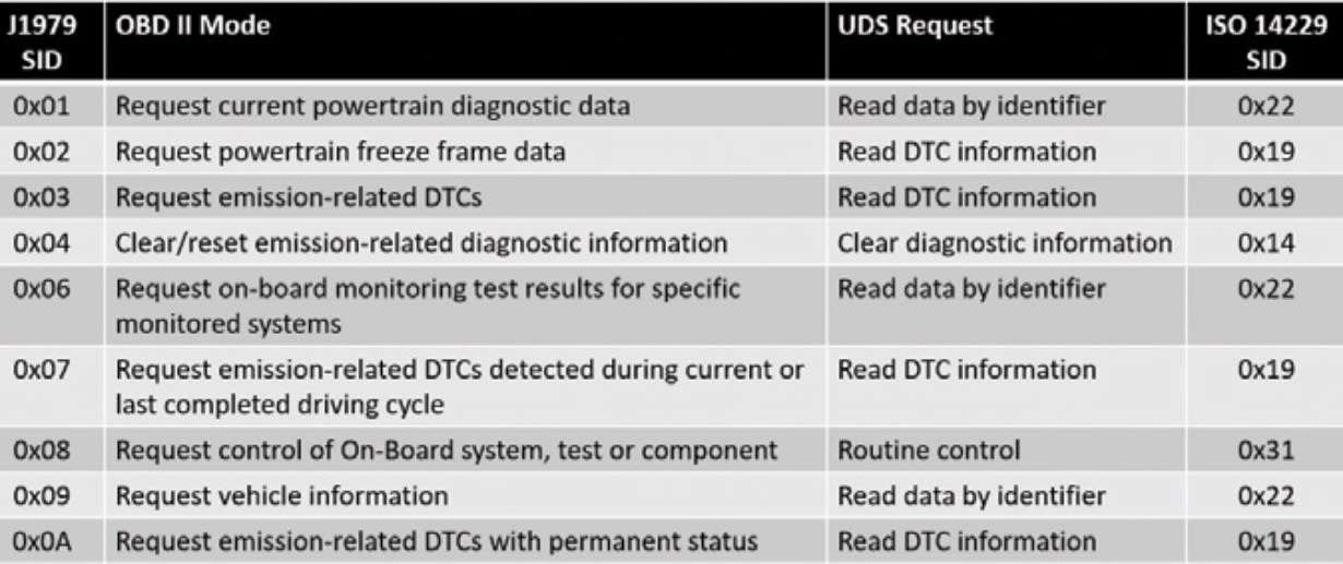
Figure 4 shows the 26 Unified Diagnostic Services (UDS) as they are specified in ISO 14229-1. The services can be parameterized by sub-function bytes and/or Data Identifiers (DIDs). Figure 5 shows that the nine SAE J1979 OBD II Modes can be replaced by four ISO 14229- 1 services. For example: OBD II Mode with the SID 0x09 = “Request vehicle information” and the PID 0x02 will be replaced by the UDS Request 0x22 = “Read data by identifier” and the 2-byte Data Identifier 0xF802. Both positive responses will contain the Vehicle Identification Number (VIN) of the vehicle.
Because ZEVonUDS covers vehicles with no emissions, the emission-related failures are replaced by ZEV propulsion-related failures. The OSI Layer 6 of both SAE J1979-2 and -3 reference several other SAE Recommended Practices and their Digital Annexes (DA) (see Figure 6).

J1979-2 and -3 differentiate two DTC (diagnostic trouble code) formats: SAE_J2012_DTCFormat_04 and SAE_ J1939-73_DTCFormat. An ECU shall only support one DTC format. SAE J1979-2 and -3 are applicable for passenger cars with SAE J2012 DTCs as well as for heavy-duty trucks with SAE J1939 DTCs. If a vehicle or engine uses DTCs in the SAE J1939 format, they can be encoded using SAE J1939 SPNs (Suspect Parameter Numbers) as they are listed in SAE J1939 DA with FMIs (Failure Mode Identifiers) defined in SAE J1939-73 Appendix A.
The SAE J1979 OBD II Modes will be replaced by new UDS-based service requests. Even if the lower OSI model layers for both old and new protocol stacks remain the same, vehicle manufacturers and their E/E system suppliers as well as tool suppliers must upgrade their technology. A mixture of J1979 and UDS-based protocols is no longer allowed. This is a major step in the direction of finally having only one world-wide harmonized diagnostic protocol: UDS on IP.
Peter Subke, director business development at Softing Automotive Electronics GmbH, wrote this article for Truck & Off-Highway Engineering.
More From SAE Media Group
Tech Briefs
Videos of the Month
Off-Highway Engineering
Mellor Bus Stresses Lightweight Construction for New Midsized Battery-Electric Buses
Automotive Engineering
Engineering ‘Electron Guzzlers’
Off-Highway Engineering
Volvo CE Previews ConExpo 2023 Display
Autonomous Vehicle Engineering
Volvo Leads the Shift to ‘Driver Understanding’
Off-Highway Engineering
Combustion Engines Carry on in Construction
Automotive Engineering
Making over the World’s Leading Hybrid
Off-Highway Engineering
New Holland Electric Mini-Excavator Hits Market
Automotive Engineering
Denso Exhibits More Compact HVAC Design at NAIAS
Tech Briefs
EV vs. ICE: How Does Wire Harness Design Differ?
NASA Spinoff
View from the Sky Helps Predict Crop Yields

Tech Briefs
Top 10 Most-Read Tech Briefs Stories of 2022
Automotive Engineering
Mazda Pushes the Propulsion Frontier
Off-Highway Engineering
Response to More-Rigid NOx and GHG Regs
Automotive Engineering
Fuel-Economy and Greenhouse-Gas Emissions Rules Debated
Battery & Electrification Technology
Ultracapacitor Solutions to Address Energy-Storage Needs of Vehicles
Automotive Engineering
Volvo’s Electric High-Wire Act
Off-Highway Engineering
Hexagon Agility Partners with Brudeli for Hybrid CNG Truck Powertrains
Automotive Engineering
AVSC Develops Best Practices for Traceable AV Safety Inspection Protocols
Automotive Engineering
New Technology for Exhausting Jobs
Automotive Engineering
SEMA Moves Powertrain Parts Certification Program to Forefront
Off-Highway Engineering
Protecting a Cyber-Physical Remote Diagnostic Communication System Against Cyberattacks
Battery & Electrification Technology
Upcycling Commercial Fleets into Circular EVs
Battery & Electrification Technology
Putting a New ‘Charge’ in EV Recharging
Off-Highway Engineering
Detailing Kenworth’s Sleek SuperTruck 2
Automotive Engineering
CARB: 54.5 Mpg CAFE Not Enough to Spur EV Technologies
Automotive Engineering
2016 Preview: Driving Continental’s 48-V Hybrid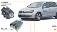

Automotive Engineering
Tula Turns Its Tech Toward EV Motor Control
Top Stories
INSIDERDesign
![]() How Airbus is Using w-DED to 3D Print Larger Titanium Airplane Parts
How Airbus is Using w-DED to 3D Print Larger Titanium Airplane Parts
NewsSensors/Data Acquisition
![]() Microvision Aquires Luminar, Plans Relationship Restoration, Multi-industry Push
Microvision Aquires Luminar, Plans Relationship Restoration, Multi-industry Push
INSIDERManned Systems
![]() A Next Generation Helmet System for Navy Pilots
A Next Generation Helmet System for Navy Pilots
NewsAR/AI
![]() Accelerating Down the Road to Autonomy
Accelerating Down the Road to Autonomy
INSIDERDefense
![]() New Raytheon and Lockheed Martin Agreements Expand Missile Defense Production
New Raytheon and Lockheed Martin Agreements Expand Missile Defense Production
ArticlesAR/AI
![]() CES 2026: Bosch is Ready to Bring AI to Your (Likely ICE-powered) Vehicle
CES 2026: Bosch is Ready to Bring AI to Your (Likely ICE-powered) Vehicle
Webcasts
Transportation
![]() Advantages of Smart Power Distribution Unit Design for Automotive...
Advantages of Smart Power Distribution Unit Design for Automotive...
Automotive
![]() Quiet, Please: NVH Improvement Opportunities in the Early Design...
Quiet, Please: NVH Improvement Opportunities in the Early Design...
Electronics & Computers
![]() Cooling a New Generation of Aerospace and Defense Embedded...
Cooling a New Generation of Aerospace and Defense Embedded...
Power
![]() Battery Abuse Testing: Pushing to Failure
Battery Abuse Testing: Pushing to Failure
AR/AI
![]() A FREE Two-Day Event Dedicated to Connected Mobility
A FREE Two-Day Event Dedicated to Connected Mobility