


Modeling Electric Motors
How to develop a traction drive using a multiphysics-based approach with 3D modeling and simulation.
From automotive and aerospace to heavy equipment, the design and development of electric motors have become an industry make-or-break issue. Not only are high performance, robustness, and efficiency at the top of the requirements list, the cost of manufacturing, materials and maintenance are also vital factors in the design and development process.
Development of a new design is more than just ensuring the motor’s efficient electromagnetic performance. Linked closely to performance is the design of the cooling system, which requires coupled thermal simulations, and the motor drive system using power electronic simulators, as well as the mitigation of noise and vibration using structural analysis. Beyond these, additional factors such as the impact of drive cycles also need to be incorporated into design development.
This article will look at an example of using some of the latest software technology to design a traction-drive motor for a medium-duty delivery truck.
Simulation approaches
The design of traction motors is a multi-stage process in which multiple design candidates are filtered through an iterative process. The technical or simulation requirements change at each stage of design. At the onset, fast and approximate results that do not take system details such as material non-linearities into account may suffice. Under most circumstances, 2D or 2.5D simulation models are also adequate during this stage. However, as the design candidates are narrowed down, deeper analysis of their performance is needed that includes the effects of non-linearities, electromagnetic losses, material property variations and the stress and force distributions, among other aspects. At this stage, detailed electromagnetic and multi-physics analyses are needed.
For electromagnetic design and analysis, two approaches are generally used. The first is a magnetic-circuit-based formulation of a model. This approach provides fast but approximate results of model performance. Another possibility is to use semi-analytic, equivalent-circuits–based models. In this method, an electrical equivalent circuit of a model is considered for which the resistance and the inductances of the model components may be obtained using static FEA-based calculations. Though not as fast as magnetic-circuits–based models, it is a good method for taking some of the non-linearities of the system into account from the early stages of design.

The second main analysis approach for machine simulations is the FEA method to create high-fidelity models of devices. The FEA-based approach solves the complete electromagnetic field problem of a model and considers nonlinear material behavior, field leakage, and other fringe effects caused by geometric details. This method is generally applied during the later stages of the design process once the number of design candidates for an application has narrowed. FEA is widely regarded as the industry standard for accuracy, and almost every electromagnetic device design candidate needs to be validated using this methodology before prototyping.
Case-study designs
For this example, developers used the specifications for a North American Class 4 delivery truck weighing between 14,001 to 16,000 lb (6,351 to 7,257 kg). Traction-drive specifications for the truck are shown in Table 1. Three designs were considered that are being actively researched for commercial applications in the traction motor industry. The first design candidate is a 10-pole 12-slot fractional slot concentrated winding machine (FSCW) motor. These machines have generated a great deal of interest recently because of their high power density, manufacturability, and wide speed ranges.
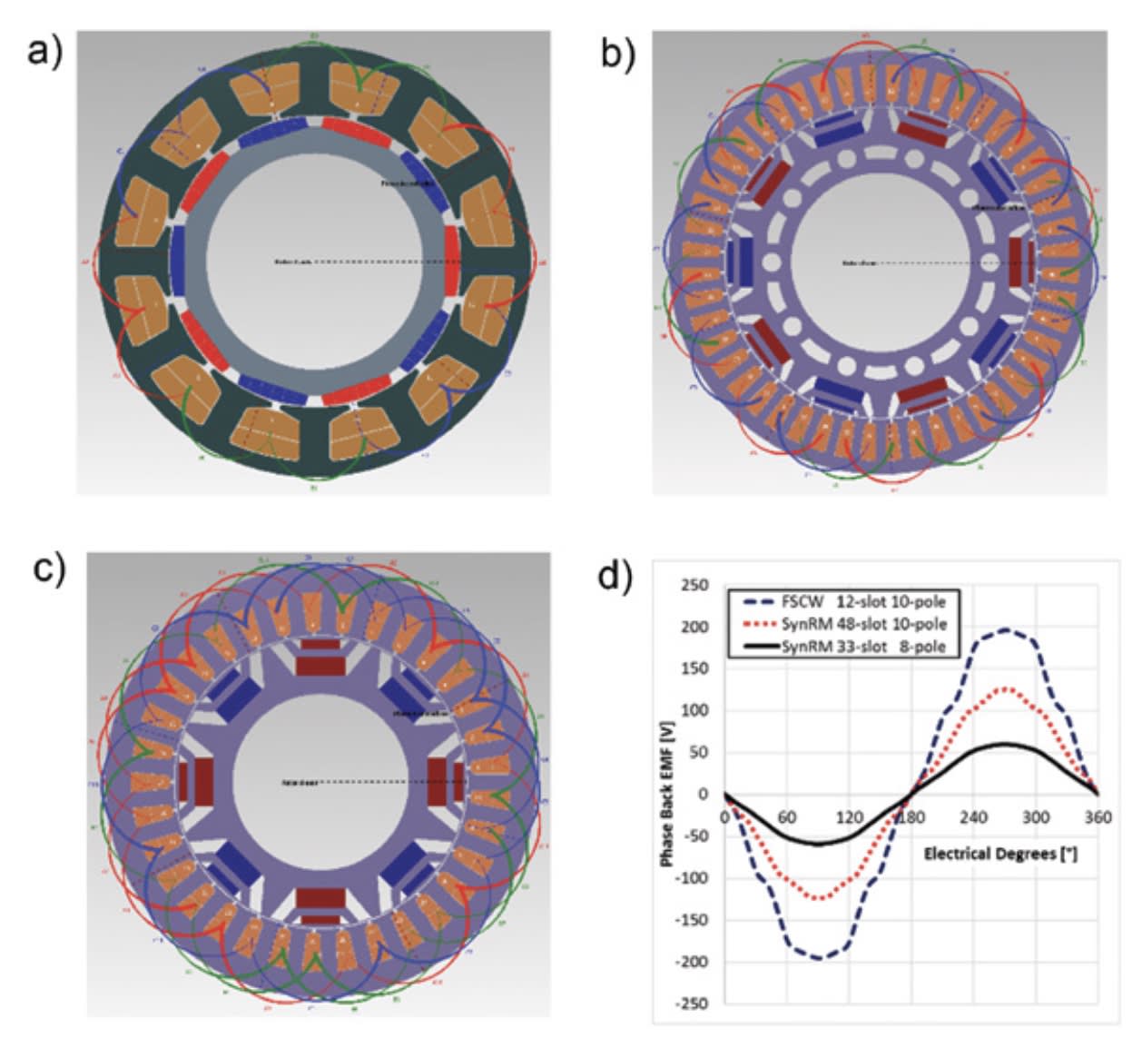
The second design is for a synchronous reluctance motor (SynRM). Engineers have been looking at the use of these motors to reduce reliance on rare-earth permanent magnet-based machines for traction applications. For a given size, SynRMs are less powerful compared to rare-earth-based motors. To overcome this, relatively less expensive permanent magnets (alnicos or ferrites) are used within the flux barriers to increase the torque of the machine and extend their maximum range, without significantly increasing costs. Two SynRM configurations were considered for this study. A cross-section of each model with some back electromagnetic force (EMF) results are shown in Figure 1.
These designs were obtained using the Simcenter Motorsolve software. They were selected from a study that considered a vast number of candidates. To reduce the number of options, fast, semi-analytical FEA-based calculations were done to obtain the machines’ electromagnetic performance parameters.
Once the three candidates were selected, some important results were obtained to compare their suitability for the application on hand. This includes typical performance parameters such as the output torque and power, machine efficiency, machine back EMF, torque-speed characteristics, efficiency maps, etc. Table 2 summarizes the electromagnetic performance parameters. At this stage, the software was used to conduct 2.5D FEA-based transient analysis.
Validation results


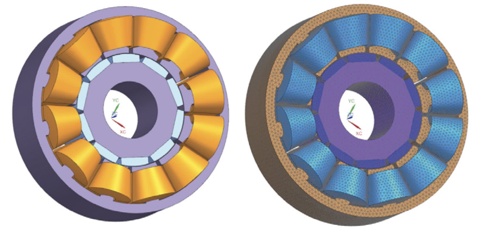
To validate the electromagnetic performance further, detailed 3D FEA-based analysis using 3D low-frequency electromagnetics simulations were performed (see lead image). In addition to electromagnetic performance, as mentioned earlier, multiphysics analysis needs to be applied to design cooling systems that maintain machine temperatures at appropriate levels. Coupled electromagnetic-thermal simulations were performed for each of these machines, and the thermal performance of each was validated. An important design consequence from this study was the need to segment the FSCW machine’s permanent magnets. This was necessary to lower the eddy current losses that can demagnetize them under normal operations. Figure 2 shows the effects of segmentation on the FSCW candidate.
Besides the need for segmentation, susceptibility to demagnetization of the design candidate’s magnets were also evaluated using the software. The results are presented in Figure 3. The results show that the FSCW and the 8/33 PMa SynRM are free from demagnetization, whereas the 10/48 PMa SynRM has a low probability of demagnetization for the thinner, outer magnet segment. For industrial applications, the rotor of this motor may have to be redesigned to mitigate this possibility.
A fast acoustic analysis of the design candidates was also done to compare their noise levels. This can be useful to determine the acoustic characteristics of the final product and if additional sound signatures might need to be considered for further design iterations. This part of the simulation was based on the mechanical forces on the machine stator structure in the air gap of the machine. The results of the analytics-based calculations are shown in Table 3.

For a more detailed structural and acoustics analysis, the force distributions in the air gap were exported to a commercial stress-analysis tool that can be used to simulate the transient noise and vibration levels of the machines.
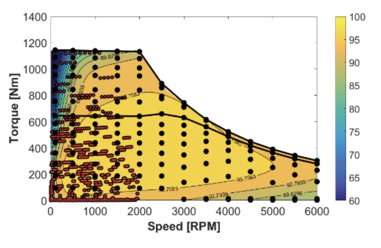
Starting with some design objectives, we walked through a sequence of typical steps needed to create a traction motor drive. The effects of the drive cycle were mentioned previously as an important test to gauge the suitability of design options. To compare vehicle performances with respect to each design candidate, dynamic vehicle simulations must be performed of the drivetrain, including the motors, for various drive cycles. In this case, the simulations can be done on any platform that facilitates dynamic vehicle simulations. The motor is generally represented on this software by its torque-speed-efficiency maps. An example of the efficiency map including the operating points for the NYCC drive cycle is shown in Figure 4 for the FSCW motor.

For the three design options, vehicle dynamic simulations were performed for several drive cycles by exporting their efficiency maps. The results are shown in Table 4. The discussions and the results presented in this article show the complexity of the process as well as illustrate the usefulness of some of the simulation and analysis tools available for design iteration that enable the inclusion of various factors affecting the motor’s application early in the development process.
Dr. Tanvir Rahman has been an R&D consultant in software engineering at Mentor Infolytica, a Siemens Business, since 2016. This article is based on a paper, “Comparison of Fractional-Slot Concentrated Winding and PM-Assisted Synchronous Reluctance Motors for Class IV EVs,” by Rahman, Mohammad Mohammadi, Kieran Humphries and David Lowther.
More From SAE Media Group
Automotive Engineering
Schaeffler Builds an E-Motor Powerhouse
Battery & Electrification Technology
Modeling Considerations for Optimizing EV Motors
Battery & Electrification Technology
The Future of Axial- and Radial-Flux Motors
Power Electronics INSIDER
Highly Conductive Aluminum Can Equal Copper
Automotive Engineering
The Inside Story on Rotary Position Sensors for Electric Vehicle Traction Motors

Automotive Engineering
Thermal Management Lies at the Heart of EV Innovation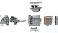
Automotive Engineering
Schaeffler Promotes E-Motor Manufacturing Flexibility
Automotive Engineering
A Lesson in Multiphysics
Battery & Electrification Technology
New Products
Battery & Electrification Technology
Using Silver Sintering in Traction Inverter Assembly
Automotive Engineering
Tula DMD Aims for More-Efficient E-Machines
Motion Design
High-Efficiency Megawatt Motor
Power Electronics INSIDER
An Electrifying Improvement in Copper Conductivity
Power Electronics INSIDER
World’s Strongest Battery Paves Way for Light, Energy-Efficient Vehicles
Medical Design Briefs
High-Power Electrostatic Actuators to Realize Artificial Muscles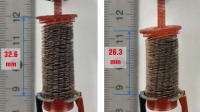
Automotive Engineering
Unifying Design and Multiphysics Simulation for Electric Drive Development
Motion Design
Navigating the Challenges of Motor Commutation
Automotive Engineering
Keeping Your Silicon Cool
Aerospace & Defense Tech Briefs
What’s the Best DC Motor for Your Commercial Aerospace Application?
Medical Design Briefs
Why Frameless Motors Are at the Forefront of the Surgical Robotic Revolution


Tech Briefs
Method Recharges an Electric Car as it Drives

Battery & Electrification Technology
The Road to Net-Zero EV Development Labs
Automotive Engineering
Model-Based Analysis of E-Motor Designs
Power Electronics INSIDER
World’s Fastest, Low-Cost, Ultraefficient Silicon Carbide Power Module
Top Stories
INSIDERManufacturing & Prototyping
![]() How Airbus is Using w-DED to 3D Print Larger Titanium Airplane Parts
How Airbus is Using w-DED to 3D Print Larger Titanium Airplane Parts
INSIDERManned Systems
![]() FAA to Replace Aging Network of Ground-Based Radars
FAA to Replace Aging Network of Ground-Based Radars
NewsTransportation
![]() CES 2026: Bosch is Ready to Bring AI to Your (Likely ICE-powered) Vehicle
CES 2026: Bosch is Ready to Bring AI to Your (Likely ICE-powered) Vehicle
NewsSoftware
![]() Accelerating Down the Road to Autonomy
Accelerating Down the Road to Autonomy
EditorialDesign
![]() DarkSky One Wants to Make the World a Darker Place
DarkSky One Wants to Make the World a Darker Place
INSIDERMaterials
![]() Can This Self-Healing Composite Make Airplane and Spacecraft Components Last...
Can This Self-Healing Composite Make Airplane and Spacecraft Components Last...
Webcasts
Defense
![]() How Sift's Unified Observability Platform Accelerates Drone Innovation
How Sift's Unified Observability Platform Accelerates Drone Innovation
Automotive
![]() E/E Architecture Redefined: Building Smarter, Safer, and Scalable...
E/E Architecture Redefined: Building Smarter, Safer, and Scalable...
Power
![]() Hydrogen Engines Are Heating Up for Heavy Duty
Hydrogen Engines Are Heating Up for Heavy Duty
Electronics & Computers
![]() Advantages of Smart Power Distribution Unit Design for Automotive...
Advantages of Smart Power Distribution Unit Design for Automotive...
Unmanned Systems
![]() Quiet, Please: NVH Improvement Opportunities in the Early Design...
Quiet, Please: NVH Improvement Opportunities in the Early Design...