Reverse Engineering the Boeing E-3 Sentry's Secondary Flight Controls

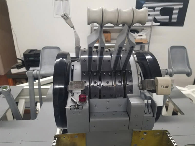
Amplify Technical Solutions was contracted to reverse engineer and manufacture a first article assembly of the secondary flight controls, focusing on the throttle quadrant and console configuration, for a NATO E-3 AWACS. The finished deliverables were part of a sophisticated flight simulator controls system being produced by Simulation and Control Technologies for an E-3 AWACS Full Flight Simulator program. The project presented challenges due to the vintage and highly evolved state of the aircraft, which required creative engineering to accurately capture and replicate the control assemblies.
The NATO E-3 AWACS has stood the test of time. The E-3 Airborne Early Warning and Control System (AWACS) was first carried aboard militarized Boeing 707 commercial aircraft with the first E-3 entering U.S Air Force service in 1977.
Throughout its history, the AWACS fleet has undergone extensive enhancements, including upgrades to radar, avionic suites, satellite communications and air traffic management. But under it all is still the old reliable 707 built between 1958 and 1979.
With many upgraded E-3s still in service, it is important to provide comprehensive pilot training based on new standards and techniques developed over the years, which includes foremost, flight simulator training. Today’s modern flight simulators, or trainers as they are called, are about as real as it gets, providing a safe learning environment without the costs and risks of putting planes in the air. Pilots can train on the latest innovations and have capabilities assessed in a controlled situation, with presentation, review and playback.
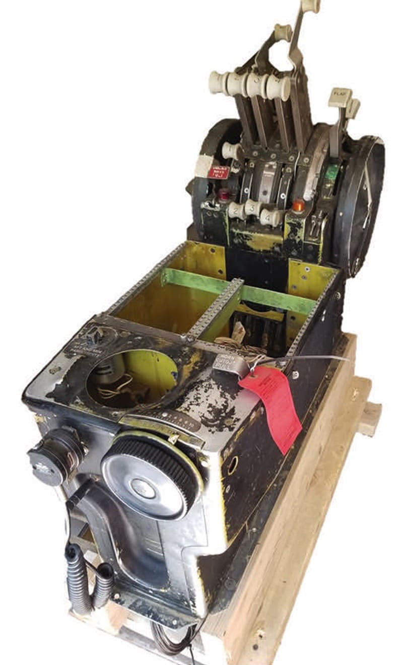
The challenge with legacy platforms like the 707 is getting ergonomic and tactile features and controls of an old aircraft into a new trainer. For this project, Government Furnished Equipment (GFE) would typically be provided to work from, but in this case, there was not much available – no spare assemblies and the bone yards had been picked clean.
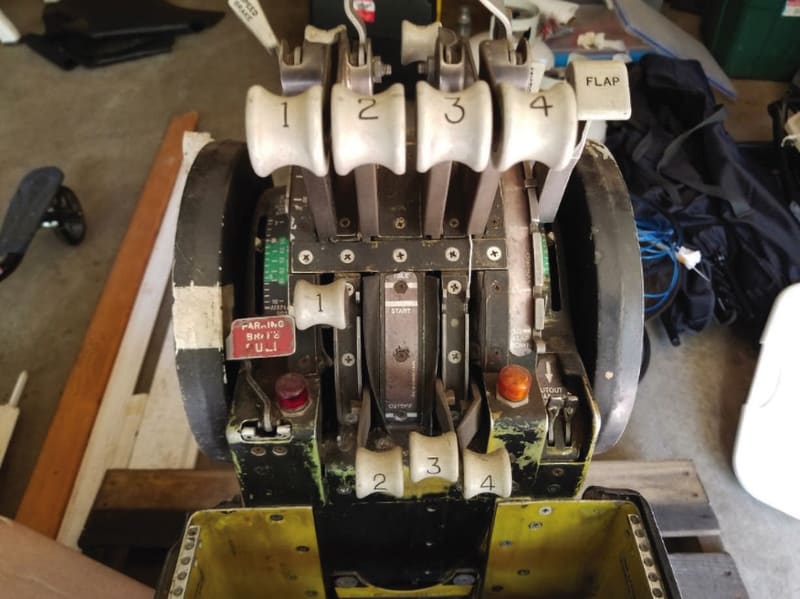
In order to recreate an exact replica of the controls for the current E-3 configuration, our team was given one-time access for three days to an existing trainer. We were also provided a single, non-working throttle quadrant from an earlier configuration that could be dissected, referenced and re-engineered to match current specs. This meant that literally every component needed to be reverse engineered and then re-engineered using photos, hand measurements, 3D scans, and measurement software.
Reverse Engineering and Re-Engineering the Throttle Quadrant
The most complex assembly of the project was the throttle quadrant containing over 300 components. The entire assembly needed to be reverse engineered, then re-engineered for design and simulator performance, within .005" tolerance or better across the entire unit. The redesigned quadrant was manufactured and given a single part number to directly replace the GFE part number referenced within the drawing package. The production package requirement for the throttle quadrant included:
Detailed CAD model
Drawing package in Native CAD format
Separate parts list in PDF and Excel format
Drawings in PDF and DWG (AutoCAD)
Complete drawing trees
Drawing delivery list
Fabrication and assembly support for first article assembly
The Reverse Engineering Toolset Used Across the Project Included:
Verisurf software for 3D scanning, touch-probing, and reverse engineering
Mastercam software for re-engineering and final CAD modeling
Creaform HandySCAN Black 3D scanner
Master3DGage, portable Coordinate Measuring Machine (CMM)
Manual measurement instruments for capturing simple geometry, friction and lever forces
Form, Fit and Function Required
When reverse engineering and re-engineering the throttle quadrant, form, fit and function was required. The geometry and surface profile of every part had to be exact. When aviating, controls are often identified by touch and feedback. Everything needs to look right, feel right, and move right.
3D Profile Scan
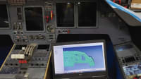
Using Verisurf software and a Creaform HandySCAN Black 3D scanner, key control elements, including the throttle quadrant installed in the reference trainer, were scanned in high-resolution. Verisurf software was then used to convert captured point cloud data to a triangular mesh model. From there, individual parts relative to the assembly could be isolated, extracted, measured and modeled to CAD, within the software. Reference entities such as points, lines, and circles, as well as geometric features including planes, cylinders, slots, cones, and spheres could be extracted and applied as individual features of reverse engineered parts.
The software’s ability to measure and compare centricity illustrated variations up to .030" – which in this project is like a football field – across the barrel-shaped base that guides the throttle levers. Each of the throttle levers also had unique geometry that had to be taken into consideration, including the profile of each throttle guide plate relative to the curved base. Every nuance of the controls had to be exact. The form, features and functions of the trainer, compared to the actual cockpit, needed to fit like an old glove.
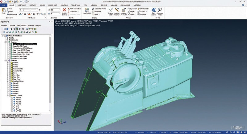
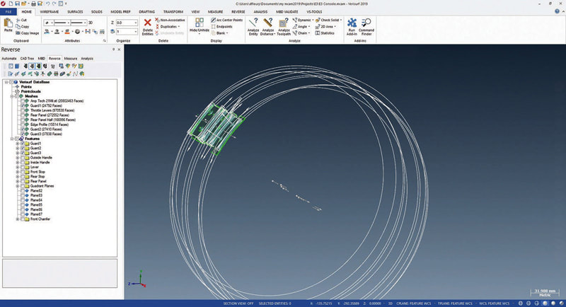
Each of the captured parts making up the overall profile were committed to CAD and any design variations added to comply with the E-3 version the trainer was meant to emulate. The challenge now was to make the quadrant move and feel right while providing input to the actuators interfacing with the simulation software.
Re-Engineering for Functionality and Performance
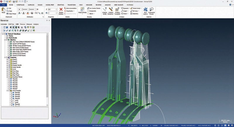
Having fully dissected the scan data from the reference trainer and committed the visible features to CAD, it was now time to get inside the supplied legacy throttle quadrant and reverse engineer its movements. Bear in mind, aircraft controls are not made to come apart; trainers must have the same integrity and durability but must be field serviceable and be easily taken apart and put back together to minimize trainer downtime over the expected 15- to 20-year life cycle. This was a critical objective for the re-engineering process.
The throttle quadrant was completely disassembled; along the way each component was measured and documented to understand the assembly of the original GFE. This was to ensure everything was accurately represented in the CAD model to help alleviate issues between the reused components and the re-engineered components. Areas that needed acute attention for design included where components connect, touch, or interact during throttle movement. Forces and positions were accounted for, including pulley sizes, cable diameters, detents, stops, and connections to actuators.
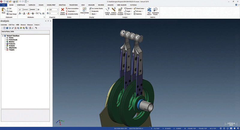
A force gauge, calipers, and a digital inclinometer were all used to measure and determine range of movement, mechanical friction and applied forces. Also noted were special areas and envelopes that need to be off limits during re-engineering. During disassembly, parts that could be used in the re-manufacturing of the quadrant were identified, including the original throttle knobs, speed brake, and flap position levers.
When re-engineering the throttle quadrant, it was critical that the system looked and behaved exactly like the legacy unit. As long as those two criteria were met, design modifications could be implemented inside the unit. This was important as the legacy assembly was completely mechanical and the re-engineered assembly would serve as a mechanical interface to a digitally controlled trainer.
Typically, reverse engineering processes are applied to a part or individual component, removed from an assembled system. This allows the entire geometry to be captured using measurement software and CMMs with touch probes or non-contact scanners. Using Verisurf software, the process is fast, accurate and very comprehensive. Isolated parts are quickly converted from point clouds to intelligent CAD models.
Reverse Engineering Software
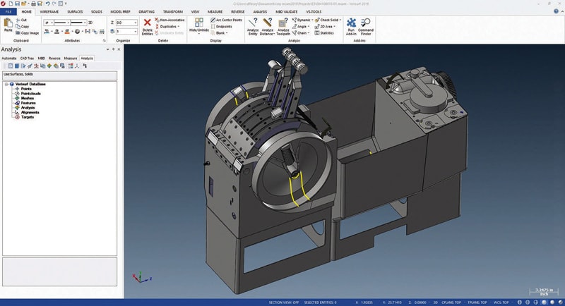
In the case of the E-3 throttle quadrant, the value of the Verisurf software took on an increased level of importance, especially given the stated overall profile tolerances of .005" all around.
The software was able to capture high-resolution point cloud data and create a watertight mesh model, effectively connecting all the assembled components and features as they relate to the overall assembly;
Verisurf software was able to isolate features, extracting only selected geometry to be converted into intelligent CAD files;
After converting scan data to CAD models, Mastercam was used to assemble all parts into a final CAD assembly file.
A project such as this cannot be done using “just” CAD. Most CAD systems can handle small scan data files imported directly into their system as an STL mesh surface and converted to a usable model file. In this case, the scan included many parts scanned as an assembly, which creates a very complex data set. A CAD system would be able to open this data file eventually, with enough power, but all the data points would be converted into a polygon mesh, giving you an approximation of the surfaces scanned. CAD systems see this polygon mesh as geometry/surfaces, which bogs the system down to a crawl and only allows data points to be taken from exterior/intersecting mesh points of the polygon. This greatly reduces the precision of the measurement and anyone who has done it knows that it can take hours to get very little data from these files.
Verisurf software can manipulate that same data with ease, allowing captured features to be accurately extracted and converted to intelligent CAD. Individual points can be completely isolated from the main scan. Measurements can be taken, and edges and planes can be referenced, before exporting the feature to CAD. This ability of Verisurf software to break down complex scan data to individual components was instrumental in reverse engineering the throttle quadrant and console.
When reverse engineering complex assemblies, it is important to have tool options. For some components, hand measuring and 3D modeling is all that is necessary, but in the case of recreating complex surface profiles and extracting features to CAD, the right measurement and reverse engineering software can be invaluable.
This article was written by David Fleury, President, Amplify Technical Solutions LLC (Leonardtown, MD). For more information, visit here . For more information about the Verisurf Software referenced in this article, visit here .
Top Stories
INSIDERRF & Microwave Electronics
![]() FAA to Replace Aging Network of Ground-Based Radars
FAA to Replace Aging Network of Ground-Based Radars
PodcastsDefense
![]() A New Additive Manufacturing Accelerator for the U.S. Navy in Guam
A New Additive Manufacturing Accelerator for the U.S. Navy in Guam
NewsSoftware
![]() Rewriting the Engineer’s Playbook: What OEMs Must Do to Spin the AI Flywheel
Rewriting the Engineer’s Playbook: What OEMs Must Do to Spin the AI Flywheel
Road ReadyPower
![]() 2026 Toyota RAV4 Review: All Hybrid, All the Time
2026 Toyota RAV4 Review: All Hybrid, All the Time
INSIDERDefense
![]() F-22 Pilot Controls Drone With Tablet
F-22 Pilot Controls Drone With Tablet
INSIDERRF & Microwave Electronics
![]() L3Harris Starts Low Rate Production Of New F-16 Viper Shield
L3Harris Starts Low Rate Production Of New F-16 Viper Shield
Webcasts
Energy
![]() Hydrogen Engines Are Heating Up for Heavy Duty
Hydrogen Engines Are Heating Up for Heavy Duty
Energy
![]() SAE Automotive Podcast: Solid-State Batteries
SAE Automotive Podcast: Solid-State Batteries
Power
![]() SAE Automotive Engineering Podcast: Additive Manufacturing
SAE Automotive Engineering Podcast: Additive Manufacturing
Aerospace
![]() A New Approach to Manufacturing Machine Connectivity for the Air Force
A New Approach to Manufacturing Machine Connectivity for the Air Force
Software
![]() Optimizing Production Processes with the Virtual Twin
Optimizing Production Processes with the Virtual Twin
