


New Honing Technology Improves Aerospace Accuracy
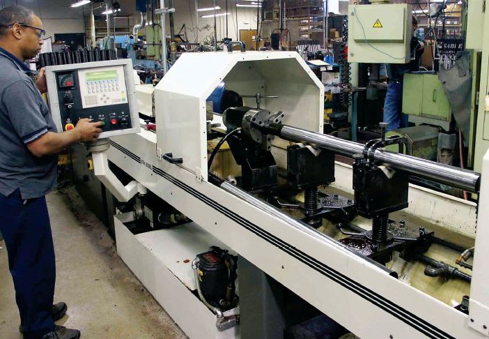
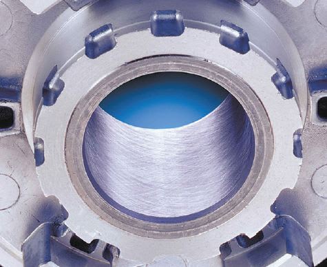
Invented more than 70 years ago to de-glaze cylinder bores in early automobile engines, conventional honing today is meeting the most advanced aerospace requirements for ultra-precise machined parts. Computer controls, new tool designs, new abrasives, integrated air-gage part measurement, and servo-driven tool feed systems and spindles enable new honing machines to produce part bores with 0.000010-inch accuracy and crosshatched surface finishes targeted to a very narrow range. Honing can even correct bore geometry distortion from upstream machining processes, welding, or heat treating. And while most users want a uniform round shape in a bore, honing can also impart a shape, such as a barrel, in a selected region of a bore if desired.
Tighter Tolerances
The aerospace industry is constantly tightening the requirements for parts to achieve lighter weight and, particularly, greater performance from end products — higher power densities, more precise control, tighter sealing, less hysteresis, noise, and vibration. Flight control systems are a good example. The ultra-high performance hydraulic valves in these systems are about 125 to 250 mm (5 to 10 inches) long, with a bore of about 12 mm (0.5 inch) diameter, including numerous lands and crossholes. Honing is used to produce bore diameter tolerances of 0.00025 mm to 0.0005 mm (0.000010 to 0.000020 inches). In fact, some parts are produced to tolerances beyond the measuring capability of many gages. In addition to sizing and finishing the bore, honing perfects the roundness, straightness, and finish of the bore. These valves operate with a clearance of 0.005 mm (0.0002 inch) or less between the valve body and matchground plunger. The same holds true for the moving parts in the pumps that power these systems. As operating clearances between moving parts shrink, honing can tightly control the bore’s surface finish to retain a lubricating film of oil.
Similarly, the bores of hydraulic accumulators are honed to eliminate any surface flaws that could propagate into cracks under stress. The bores of fuse pins, used at the attachment points of engine pylons, are honed to precise size and finish tolerances to ensure they shear under the correct level of stress. Multiple components in ram-air turbines are honed, as are the bolt holes in turbine hubs and discs. The bores of gears used by Airbus, Boeing, Cessna, and NASA are honed for similar reasons.

New Tool Feed Technology
Typically, a production honing process is set up to use an abrasive tool with a specific grit size and bond optimized for incoming part conditions. Tool expansion to achieve the desired results and final size is programmed based on rate of time. The tool feed system performs the same way on each cycle, starting with touch-off, sensed through spindle load or the force sensed on the tool feed system. Cycle time is always the same. However, when a batch of parts comes in with a different heat treatment, distortion, or a size variation, the operator must intervene because the tool may expand too quickly for part conditions and be damaged. In the opposite case with a softer-than-normal workpiece, the tool will still expand at its programmed rate when it might have been able to expand faster to reduce cycle time. Expansion at too slow a rate may also result in glazing of the honing stones, which won’t self-dress if the cutting force is too low. Typically, the operator must tweak the feedrate periodically to compensate for these variables.
With Controlled-Force honing, the machine still uses a programmed feedrate, which is then increased or decreased to maintain a setpoint for the force load on the tool feed system. If the feed force drops off, the system increases the tool feed rate to compensate — resulting in faster cycle time, as just one example. Feed force is monitored every few milliseconds during the cycle to ensure the tool always feeds at the highest rate possible for part conditions.
In a typical scenario on a small pump bore, the tool expands rapidly at the start of the cycle until the system senses 150 N of force, and then climbs gradually to its 200 N setpoint.

Controlled force honing also produces more consistent surface finish results. In one application with hard steel parts, standard rate-feed honing produced Rz values of 2 to 7 μm. With Controlled- Force honing, the process consistently holds Rz between 5 to 6.5 μm.
Controlled-Force honing sometimes allows use of harder, more durable abrasive bonds, where softer bonds may have been required in the past. As a result, the part yield for a given set of abrasives increases, while the abrasive cost drops. Likewise, Controlled-Force technology eliminates glazing of the abrasive, due to too little cutting force. This ensures a steady, free-cutting, self-dressing condition for maximum metal removal in the shortest possible cycle time.
Connecting rods illustrate the advantage in honing parts with varying wall thickness. The con rod has the beam on one side — so the rod is very rigid in this thicker area — and the cap on the other side where wall thickness is considerably thinner. As a result, the bore has a tendency to distort more in the weaker area during honing. On these workpieces with irregular wall thickness, Controlled- Force ensures the system never overloads the tool and distorts the bore.
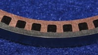
Rate feed will still be the exclusive tool feed methodology with certain honing tools that use a full wraparound sleeve of metal-bonded diamond abrasive — rather than segments of abrasive — for full contact with the bore surface. These tools are particularly useful for bridging segmented bores, multiple lands, ports, keyways, or crossholes. Controlled-rate feeding provides up to five expansion profiles that can be used during a cycle for rapid part touch, cutting, sizing, finishing, and spark-out.
This article was written by Dennis Westhoff, Business Development Manager, Sunnen Products Company (St. Louis, MO). For more information, Click Here .
More From SAE Media Group
Aerospace Manufacturing and Machining
CAM Software Technology Keeps Pace with Aerospace Manufacturing Challenges
Aerospace & Defense Tech Briefs
Evaluation of Additively Manufactured Ultrahard Steels
Tech Briefs
Thermal Bypass Valves
Aerospace & Defense Tech Briefs
Streamlining Post-Processing in Additive Manufacturing

Aerospace & Defense Tech Briefs
Making the Rounds in Aerospace: Tooling and Techniques for Discs, Blisks and Rings
Tech Briefs
Automated Tow/Tape Placement System
Aerospace & Defense Tech Briefs
Improving the Surface Finish of Additive Manufactured Parts
Aerospace & Defense Tech Briefs
Additive Manufacturing
Aerospace Manufacturing and Fabrication
New Products & Services
Aerospace & Defense Tech Briefs
Aerospace Production: Overcoming Challenges in Composite Machining
Aerospace & Defense Tech Briefs
Cold Spray Technology

Aerospace & Defense Tech Briefs
Dry Drilling Composites Using Carbon Dioxide Cooling
Aerospace Manufacturing and Machining
Does Your Coating Thickness Meet Spec?
Aerospace & Defense Tech Briefs
Robotic Rotational Molding Creates New Opportunities for Military and Aerospace Applications
Aerospace & Defense Tech Briefs
Automated drilling machine takes the burr out of fuselage joint

Aerospace & Defense Tech Briefs
Physics-Guided Neural Network for Regularization and Learning Unbalanced Data Sets
Aerospace & Defense Tech Briefs
Machining Beryllium

Aerospace & Defense Tech Briefs
SAE International Extends Call for Abstracts, Seeks Submissions for AeroTech Conference
Aerospace & Defense Tech Briefs
Improving Component Life in Abrasive, Corrosive Aerospace Environments
Aerospace & Defense Tech Briefs
Novel Whisker Mitigating Composite Conformal Coat Assessment


Aerospace INSIDER
Air Force Wind Tunnel Team Takes 3D Printing Program to Next Dimension
Top Stories
INSIDERManufacturing & Prototyping
![]() How Airbus is Using w-DED to 3D Print Larger Titanium Airplane Parts
How Airbus is Using w-DED to 3D Print Larger Titanium Airplane Parts
INSIDERManned Systems
![]() FAA to Replace Aging Network of Ground-Based Radars
FAA to Replace Aging Network of Ground-Based Radars
NewsTransportation
![]() CES 2026: Bosch is Ready to Bring AI to Your (Likely ICE-powered) Vehicle
CES 2026: Bosch is Ready to Bring AI to Your (Likely ICE-powered) Vehicle
NewsSoftware
![]() Accelerating Down the Road to Autonomy
Accelerating Down the Road to Autonomy
EditorialDesign
![]() DarkSky One Wants to Make the World a Darker Place
DarkSky One Wants to Make the World a Darker Place
INSIDERMaterials
![]() Can This Self-Healing Composite Make Airplane and Spacecraft Components Last...
Can This Self-Healing Composite Make Airplane and Spacecraft Components Last...
Webcasts
Defense
![]() How Sift's Unified Observability Platform Accelerates Drone Innovation
How Sift's Unified Observability Platform Accelerates Drone Innovation
Automotive
![]() E/E Architecture Redefined: Building Smarter, Safer, and Scalable...
E/E Architecture Redefined: Building Smarter, Safer, and Scalable...
Power
![]() Hydrogen Engines Are Heating Up for Heavy Duty
Hydrogen Engines Are Heating Up for Heavy Duty
Electronics & Computers
![]() Advantages of Smart Power Distribution Unit Design for Automotive...
Advantages of Smart Power Distribution Unit Design for Automotive...
Unmanned Systems
![]() Quiet, Please: NVH Improvement Opportunities in the Early Design...
Quiet, Please: NVH Improvement Opportunities in the Early Design...