


Inside the Navy’s Quiet Water Tunnel Facility
When water flows over an acoustic sensor, non-acoustic pressure fluctuations caused by turbulence can decrease the signal-to-noise ratio and make it difficult to sense incoming acoustic waves. The Quiet Water Tunnel Facility at the Naval Undersea Warfare Center in Newport, RI is a unique test facility capable of investigating these pressure fluctuations and evaluating new and existing technologies aimed at reducing flow noise and drag due to skin friction. These technologies include modifications to the surface itself, such as riblets or compliant coatings, or modifications to the flow, such as suction or injection of water into the boundary layer.
Background

The Quiet Water Tunnel depicted in the accompanying diagram is a recirculating flow facility that contains approximately 2000 gallons (7600 liters) of fresh water. Mass flow is controlled by a 745.7 watt induction motor that is coupled with a centrifugal pump. Maximum mass flow is approximately 3,300 gal/min (210 L/s). Static pressure is kept between 20-40 psi (140-210 kPa) during testing to prevent pump cavitation, and water temperature can be maintained from 60-90 °F (15.5-32 °C) with a counterflow heat exchanger.
As seen in the diagram, circular and rectangular test sections are installed in parallel and can be run independently or concurrently with one another. The circular test section consists of an acrylic pipe with an inner diameter of 3.5 inches (89mm) and a wall thickness of 0.5 inch (13mm). Flow enters the pipe from a transition section which is connected to the upper plenum chamber via a rubber hose. Centerline velocities up to 80 ft/s (24.5 m/s) are possible in the circular test section, resulting in Reynolds numbers based on pipe diameter up to 2.4×10⁶. The generated boundary layer is half the pipe diameter, or approximately 1.75 inches (45mm) thick.
The rectangular test section is 83 inches (2.11 meters) long, with a constant interior width of 12 inches (305mm). In order to compensate for the growth of the boundary layers on the walls and to maintain a zero pressure gradient flow, the interior height increases from 4 inches (102mm) at the inlet to 4.41 inches (112mm) at the exit. If needed, the bottom plate of the test section can be reconfigured to establish an adverse or favorable pressure gradient. Free stream velocities up to 20 ft/s (6.2 m/s) are possible in the rectangular test section. A rectangular contraction nozzle upstream of the test section in the middle plenum chamber is used to accelerate the flow into the test section while minimizing free stream vorticity, resulting in a turbulence intensity of approximately 1% in the free stream. Also, the test section has minimal spanwise variation in the boundary layers on the top and bottom walls. The side wall boundary layers have minimal effect on measurements that are taken from the center of the channel on the top or bottom walls.
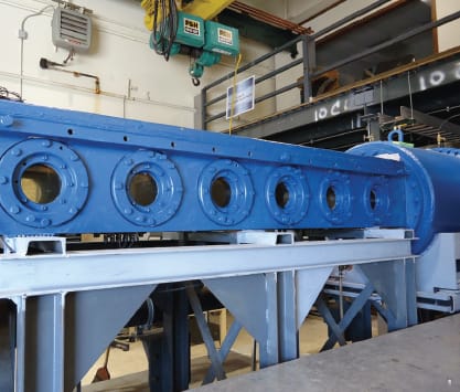
Custom instrumentation can be easily installed in each test section. Both test sections have a modular design with easily removable and replaceable fixtures. In the circular test section, sections of the acrylic pipe can be removed and replaced with instrumented sections. In the rectangular section, six ports in the top of the test section can be removed and machined in order to accommodate a variety of sensors and test fixtures, including piezoelectric wall pressure sensors, flush mounted hot film wall shear stress sensors, pitot tubes, and static pressure taps. For example, one current port has a pressure sensor array consisting of 48 tightly-spaced piezoelectric sensors flush mounted at the fluid/solid interface, allowing direct wave-number-frequency measurements of turbulent boundary layer wall pressure fluctuations to be made.
Strengths of the Quiet Water Tunnel
Among similar water tunnel and tow tank facilities, the acoustic isolation of the Quiet Water Tunnel makes it truly unique. Acoustic noise in the test sections is minimized in several ways, the foremost being the use of rubber hoses to provide vibration isolation between the major components. Also, the plenum chambers, rectangular test section, and circular test section are sufficiently structurally rigid to minimize flow induced vibration. Finally, the pump was specifically designed to minimize radiated acoustic energy. The resulting acoustic isolation allows the non-acoustic pressure fluctuations at the fluid-solid interface of a turbulent boundary layer to be studied without background noise.
Applications

Drag and flow noise reduction can be accomplished through control of the physics of the turbulent boundary layers. Various techniques for turbulence control have been tested at the Quiet Water Tunnel, including isotropic and nonisotropic compliant walls, hot and cold water injection into the boundary layer, riblet coatings, large eddy break-up devices, and thin urethane coatings. These and other efforts have also led to the development of unique instrumentation and experimental techniques.
Summary
The Quiet Water Tunnel Facility at the Naval Undersea Warfare Center in Newport, RI is specifically designed to measure the mean and fluctuating wall pressure and shear forces exerted by a turbulent boundary layer. Both the circular and rectangular test sections can be used to achieve a wide range of moderate to high Reynolds number flows. The test sections are well acoustically isolated at frequencies above those of the structural noise generated by the centrifugal pump. The Quiet Water Tunnel is a unique facility ideally suited for studying boundary layer control for drag and flow noise reduction, and is a valuable asset for basic and applied research.
This article was written by Jillian Kiser, William Keith, and Alia Foley; Devices, Sensors, and Materials R&D Branch, Naval Undersea Warfare Center (Newport, RI). For more information, Click Here .
More From SAE Media Group

Tech Briefs
Rocket Nozzle Side-Load Analysis Software
Aerospace & Defense Tech Briefs
Rotorcraft Icing Computational Tool Development
Aerospace & Defense Tech Briefs
Comparing Blade-Element Momentum Modeling to 3-D CFD
Tech Briefs
Flap Edge Noise Reduction Fins
Aerospace & Defense Tech Briefs
R/V Athena Model (5365) Response in Waves
Aerospace & Defense Tech Briefs
Surviving the Challenge of Thermal Design in Aerospace Electronics
Aerospace & Defense Tech Briefs
New Tools Bring Faster, Simpler Fluid Flow Analysis Into the Engineering Mainstream
Aerospace & Defense Tech Briefs
Aeroacoustic Simulation Delivers Breakthroughs in Aircraft Noise Reduction
Motion Control Technology
Computational Fluid Dynamics Aids Aerospace Apps
Aerospace & Defense Tech Briefs
Airflow and Thermal Analysis of UAV De-Icing Systems
Aerospace & Defense Tech Briefs
Engine Air-Brakes
Tech Briefs
Robust, Optimal Subsonic Airfoil Shapes
Aerospace & Defense Tech Briefs
Bringing Turbine Power to Small Aircraft
Aerospace & Defense Tech Briefs
UGVs — On the Cutting Edge of Thermal Management
Aerospace & Defense Tech Briefs
Model Development Using Accelerated Simulations of Hypersonic Flow Features

Aerospace & Defense Tech Briefs
Optimizing Thermal Management to Meet SWaP-C Requirements
Aerospace & Defense Tech Briefs
Characterization of Bore Temperatures and Stresses in Small Caliber Gun Barrels
Aerospace & Defense Tech Briefs
3D Printing Aerodynamic Improvements
Tech Briefs
Los Alamos National Laboratory
Aerospace & Defense Tech Briefs
Modeling and Simulation Techniques for Unmanned Vehicle Systems

Aerospace & Defense Tech Briefs
Instrumentation for Fabrication and Testing of High-Speed Single-Rotor and Compound-Rotor Systems
Aerospace & Defense Tech Briefs
Characterization of Turbulent Unsteady Separation Using Photonic Micro-Skin Friction and Wall Pressure Sensors
Aerospace & Defense Tech Briefs
Designing a High-Speed Decoy Unmanned Aerial Vehicle (UAV)
Aerospace & Defense Tech Briefs
Designing Thermal Management Systems for Smaller, Lighter Avionics

Autonomous Vehicle Engineering
The Electric, Autonomous Revolution Lifts Off
Top Stories
INSIDERManufacturing & Prototyping
![]() How Airbus is Using w-DED to 3D Print Larger Titanium Airplane Parts
How Airbus is Using w-DED to 3D Print Larger Titanium Airplane Parts
INSIDERManned Systems
![]() FAA to Replace Aging Network of Ground-Based Radars
FAA to Replace Aging Network of Ground-Based Radars
NewsTransportation
![]() CES 2026: Bosch is Ready to Bring AI to Your (Likely ICE-powered) Vehicle
CES 2026: Bosch is Ready to Bring AI to Your (Likely ICE-powered) Vehicle
NewsSoftware
![]() Accelerating Down the Road to Autonomy
Accelerating Down the Road to Autonomy
EditorialDesign
![]() DarkSky One Wants to Make the World a Darker Place
DarkSky One Wants to Make the World a Darker Place
INSIDERMaterials
![]() Can This Self-Healing Composite Make Airplane and Spacecraft Components Last...
Can This Self-Healing Composite Make Airplane and Spacecraft Components Last...
Webcasts
Defense
![]() How Sift's Unified Observability Platform Accelerates Drone Innovation
How Sift's Unified Observability Platform Accelerates Drone Innovation
Automotive
![]() E/E Architecture Redefined: Building Smarter, Safer, and Scalable...
E/E Architecture Redefined: Building Smarter, Safer, and Scalable...
Power
![]() Hydrogen Engines Are Heating Up for Heavy Duty
Hydrogen Engines Are Heating Up for Heavy Duty
Electronics & Computers
![]() Advantages of Smart Power Distribution Unit Design for Automotive...
Advantages of Smart Power Distribution Unit Design for Automotive...
Unmanned Systems
![]() Quiet, Please: NVH Improvement Opportunities in the Early Design...
Quiet, Please: NVH Improvement Opportunities in the Early Design...