


Reflected Signal Analysis
Forensic characterization of portable electronic devices helps pilots verify which devices are approved for use on aircraft.
Forensic characterization of a wireless device is useful in many applications. An example of this is in the testing of Federal Communications Commission (FCC) Part 15 devices that must adhere to strict guidelines with regard to RF interference; one reason being problems with Portable Electronic Devices (PEDs) carried onboard aircraft. The operation of PEDs aboard U.S.-registered civil aircraft is limited. These rules also permit the use of specific PEDs after the aircraft operator has determined that the PED will not interfere with the operations of the aircraft. However, how can the aircraft operator know which PEDs are approved, or if the approved devices are being operated at inappropriate times? Compliance can be verified by detecting the operation of transmitting PEDs (T-PEDs) using an onboard monitoring system, or it could be verified by characterizing the device at a gate entry point, whether powered on or off, using specially designed probe signals and forensic techniques to classify the returned signal. In a more general setting, forensic characterization allows determination of the type of device, make, model, configuration, and other characteristics based on observation of the data that the device produces. The unique characteristics of the device are known as device signatures or device fingerprints.
The waveform and modeling design has been enhanced from two previous experiments. Experiment 1 used a linear chirp signal multiplied by a Gaussian window to excite a nonlinear system model. This experiment focused on mathematical modeling of the system response and classification methods using five combinations of filters and nonlinear components. This work was conducted at Purdue University. The research was extended by developing a model for the nonlinearity based on a diode. A comprehensive analysis was performed of all possible combinations (not limited to five) of the filter and nonlinearity at several different noise levels.
Experiment 2 used a linear chirp to excite the system with a focus on large bandwidth filter responses without the presence of a nonlinearity. This experiment, initially conducted by Purdue University and North Carolina State University, encountered several hardware limitations that restricted the bandwidth of the probe to 100 MHz. To overcome this limitation, the measured reflected responses were mapped to a larger response prior to feature selection and analysis. For this experiment, the response to a large bandwidth signal is captured for analysis, and a diode is added to act as a nonlinearity in the system. This alleviates the need for mapping.
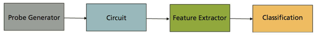
This experiment studies reflected signals resulting from a Gaussian windowed chirp exciting a combination of filter and nonlinearity models with noise added. Features were extracted from the reflected signals and then were classified using a set of known classifiers to compare the results.
Five circuit models were used in this experiment. Each nonlinearity parameter in the system is defined as ai, which is the ith coefficient in the Taylor-series. This specific parameter value was initially based on observations of an actual nonlinear response, with additional values determined to elicit a specific response.
Typical RF devices contain a “frontend” circuit, where the front end is the circuitry between the antenna and the intermediate frequency (IF) section of the circuit. The probe signal is received by an antenna, passes through a bandpass filter, and is input into an amplifier. Typically, these three components are impedance matched, which allows one to simplify the front end to the model, where the only component of interest is the bandpass filter.
While the diode model used provides a foundation for modeling nonlinearities, it still warrants further investigation. The amplitude plays a major role in the response of the nonlinearity; this parameter should be looked at in more detail. When combined with a filter, it would be of interest to observe whether the shape or the amplitude of the response plays a more significant role in classification. Also, since the filter seems to be the dominant feature in both sets of experiments, a tiered classification system should be explored. This type of system would classify based on filter first, followed by a diode-based classification.
This work was done by Deen King-Smith, Anthony Martone, and Marc Ressler of the Army Research Laboratory. For more information, download the Technical Support Package (free white paper) at www.defensetechbriefs.com/tsp under the Electronics/Computers category. ARL-0096
This Brief includes a Technical Support Package (TSP).
Reflected Signal Analysis
(reference ARL-0096) is currently available for download from the TSP library.
Don't have an account?
More From SAE Media Group
Tech Briefs
Low-Frequency Signal-Pickup Cable Tester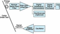
Aerospace & Defense Tech Briefs
Development of a 94 GHz Radar System for Dedicated Bird Detection at Airports and Airfields
Aerospace & Defense Tech Briefs
Advanced Satellite Communications Research
Embedded Technology
Designing Versatile COTS Data Acquisition Systems
Tech Briefs
Miniature L-Band Radar Transceiver

Aerospace & Defense Tech Briefs
Effects of High-Power Microwave Pulses on Electronic Systems
Aerospace & Defense Tech Briefs
What is Pulse Shaping?
Tech Briefs
Wireless, Wearable Transmitter


Tech Briefs
New on the Market

Tech Briefs
New Wireless System for Greater 5G Access

Tech Briefs
Loss-Tolerant Speech Codec
Electronics & Sensors INSIDER
New Transmitter Could Make Wireless Devices More Energy-Efficient


Aerospace & Defense Tech Briefs
Co-Prime Frequency and Aperture Design for HF Surveillance, Wideband Radar Imaging, and Nonstationary Array Processing
Aerospace & Defense Tech Briefs
Benefits and Challenges of Direct-RF Sampling for Avionic Platforms
Aerospace & Defense Tech Briefs
Front-End Mixed-Signal Receiver on a Chip
Aerospace & Defense Tech Briefs
Software-Defined Analog Filters: A Paradigm Shift in Radio Filter Performance and Capability

Aerospace & Defense Tech Briefs
New Products
Aerospace & Defense Tech Briefs
Qualification of Multi-Channel Direction Finding Radar Receivers in The Lab
Aerospace & Defense Tech Briefs
Optoelectronic Analog Signal Transmission Takes Center Stage Amidst Aerospace and Defense Innovation


Overview
The document titled "Reflected Signal Analysis" is a report authored by Deen King-Smith, Anthony Martone, and Marc Ressler from the U.S. Army Research Laboratory. It focuses on the forensic characterization of wireless devices, which is increasingly relevant due to the ubiquity of such devices in modern society. The report outlines the methodologies and findings from research conducted between May and September 2009.
The introduction emphasizes the importance of wireless devices in various applications, highlighting the need for effective forensic analysis to understand their behavior and interactions. The report likely discusses the principles of signal reflection and how these can be utilized to gather information about wireless communications, which can be crucial in both civilian and military contexts.
While specific details of the methodologies and results are not provided in the pages referenced, the report is expected to cover various techniques for analyzing reflected signals, including the potential for identifying device characteristics, communication patterns, and possibly even user behavior based on the signals emitted and received by these devices.
The document also includes standard disclaimers regarding the findings, indicating that they do not represent an official position of the Department of the Army unless specified otherwise. It emphasizes the importance of proper handling and destruction of the report once it is no longer needed, reflecting the sensitive nature of the information contained within.
In summary, the "Reflected Signal Analysis" report serves as a foundational document for understanding the forensic analysis of wireless devices through the study of reflected signals. It aims to provide insights that can enhance the capabilities of military and defense organizations in monitoring and analyzing wireless communications, thereby contributing to improved security and operational effectiveness. The report is intended for distribution to various defense-related organizations, indicating its relevance to ongoing research and development in the field of wireless technology and forensic analysis.
Top Stories
INSIDERManufacturing & Prototyping
![]() How Airbus is Using w-DED to 3D Print Larger Titanium Airplane Parts
How Airbus is Using w-DED to 3D Print Larger Titanium Airplane Parts
INSIDERManned Systems
![]() FAA to Replace Aging Network of Ground-Based Radars
FAA to Replace Aging Network of Ground-Based Radars
NewsTransportation
![]() CES 2026: Bosch is Ready to Bring AI to Your (Likely ICE-powered) Vehicle
CES 2026: Bosch is Ready to Bring AI to Your (Likely ICE-powered) Vehicle
NewsSoftware
![]() Accelerating Down the Road to Autonomy
Accelerating Down the Road to Autonomy
EditorialDesign
![]() DarkSky One Wants to Make the World a Darker Place
DarkSky One Wants to Make the World a Darker Place
INSIDERMaterials
![]() Can This Self-Healing Composite Make Airplane and Spacecraft Components Last...
Can This Self-Healing Composite Make Airplane and Spacecraft Components Last...
Webcasts
Defense
![]() How Sift's Unified Observability Platform Accelerates Drone Innovation
How Sift's Unified Observability Platform Accelerates Drone Innovation
Automotive
![]() E/E Architecture Redefined: Building Smarter, Safer, and Scalable...
E/E Architecture Redefined: Building Smarter, Safer, and Scalable...
Power
![]() Hydrogen Engines Are Heating Up for Heavy Duty
Hydrogen Engines Are Heating Up for Heavy Duty
Electronics & Computers
![]() Advantages of Smart Power Distribution Unit Design for Automotive...
Advantages of Smart Power Distribution Unit Design for Automotive...
Unmanned Systems
![]() Quiet, Please: NVH Improvement Opportunities in the Early Design...
Quiet, Please: NVH Improvement Opportunities in the Early Design...