


Detector Module for Testing Silicon Carbide Semiconductor Devices
This device prevents damage during testing by preventing catastrophic threshold breaches.
Long-term stress testing of silicon carbide (SiC) semiconductor devices is required to determine suitability for power electronics applications. During testing, preventable catastrophic failures can occur due to drift in steady-state operation or transients that shift the device outside of its safe operating range. Both steady-state and transient drift are easily monitored values including temperature, on-state resistance, voltage, and current, as well as others. By measuring and reacting to shifts in these values, device damage can be minimized.

This threshold detector has applicability to a wide variety of test applications through the following capabilities:
- Upper and lower window thresholds adjustable between ±l3 V, accommodating a wide range of probe or transducer output ranges and offsets.
- Latching with 10 mV*60 ns sensitivity.
- Channels can be set for window compare or single threshold detect on.
- Four inputs combined by logical AND functions.
- Low hysteresis (typically or less).
- Low noise.
- High common-mode rejection (between input and threshold references).
- Most stages are designed to fail in a safe mode.
- Optical isolation provides safety, prevents ground loops, and provides the ability to float the output stage at any voltage differential between references.
- Powered using either DC power supplies or batteries.
- Highly reliable through simple design and construction.
- Easy to troubleshoot.
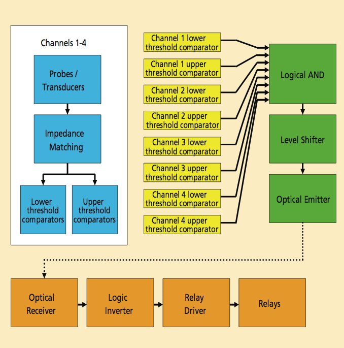
Each input channel has a user-set upper and lower threshold reference. The window comparator compares the input value to its corresponding threshold limit. In most cases, the inputs need to be impedance-matched to the source due to the high input impedance of the comparators (AD-790s).
The comparator outputs latch low during threshold events, but they can also be set to not latch onto transient events. If the detection input to U1 and U2 surpasses either reference provided by R1 or R2, the respective output of U1 or U2 will be pulled low, resulting in a low at the output of U3. The signals at U3’s inputs are discrete digital outputs from each of the comparators (see Figure 2). A low output state from the comparators indicates either a failure or an exceeded threshold.
The complementary metal oxide semiconducting field-effect transistor (CMOS) AND gate U3 provides the output signal by combining the signals from each pair of comparators. Due to the CMOS AND gate-limited current output, a high-input impedance amplifier is used to drive the optical transmitter and the light emitting diode (LED), both of which are on during a non-failure condition. The output of U3 drives the gate of a junction field effect transistor (JFET) amplifier that controls the current for a optical transmitter. This optical transmitter allows an optical link between the probe board and the relay board, providing the ability to apply different reference voltages to each board. The differential voltage level between boards is only limited by power supply isolation.
As demonstrated in a die attach power cycling experiment, the threshold detector has proven to be a reliable safety switch. The power cycling test consists of several thousand on/off cycles with durations of 5 to 30 s each. During this test, increasing diode temperature caused by device degradation or current transients causes damage to the device and die attach materials. The threshold detector prevented catastrophic failure of the SiC diodes caused by the increasing device temperature. In this experiment, the gradual temperature drift caused a drift in the forward current and forward voltage of a group of series-connected diodes. The threshold detector monitored the anode voltage of each diode using differential probes (one diode per channel). If the voltage drifted beyond a predetermined threshold, the test was shut down to prevent damage due to excessive temperature rise.
The threshold detector’s use in the power cycling experiment is one example of the potential of this circuit. This device can limit the voltage, current, and temperature of the test item. The detector can also be controlled with an external timer to allow timed testing. Scalable and optically isolated inputs and outputs make this threshold detector applicable for many tests where monitoring and automatic shutdown are required.
This work was done by Mark R. Morgenstern of the Army Research Laboratory. ARL-0073
This Brief includes a Technical Support Package (TSP).
Detector Module for Testing Silicon Carbide Semiconductor Devices
(reference ARL-0073) is currently available for download from the TSP library.
Don't have an account?
More From SAE Media Group
Power Electronics INSIDER
Superconducting Diode Bridge Efficiently Converts AC to DC for Quantum Circuits
Electronics & Sensors INSIDER
A New Magnetic Transistor for More Energy-Efficient Electronics
Tech Briefs
New on the Market

Photonics Tech Briefs
Multiple-Event, Single-Photon Counting Imaging Sensor
Electronics & Sensors INSIDER
MIT Engineers Grow “High-Rise” 3D Chips
Electronics & Sensors INSIDER
Self-Powered Sensor Automatically Harvests Magnetic Energy

Electronics & Sensors INSIDER
New Material Will Make Locally Flexible Diodes Possible
Electronics & Sensors INSIDER
A New Kind of Transistor — A Conductive Polymer
Tech Briefs
Pulsed Operation of an Ion Accelerator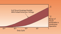
Electronics & Sensors INSIDER
The World’s First Wood Transistor
Power Electronics INSIDER
Breakthrough Iron-Based Magnetic Material for Next-Generation Power Electronics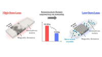
Electronics & Sensors INSIDER
Tiny But Mighty: Next-Gen Transistors Hold Great Promise
Power Management INSIDER
Clean, Limitless Power from Graphene

Tech Briefs
Microfabricated Ice Sensors
Electronics & Sensors INSIDER
Researchers Create First Functional Semiconductor Made from Graphene


Power Electronics INSIDER
Diamond Quantum Imaging Can Enable Next-Gen Power Electronics
Electronics & Sensors INSIDER
World's First Petahertz-Speed Phototransistor in Ambient Conditions
Tech Briefs
Better Microelectronics from Coal

Electronics & Sensors INSIDER
Scientists Create Superconducting Semiconductor Material
Electronics & Sensors INSIDER
New Cooling Technique Could Make Computer Chips More Powerful
Electronics & Sensors INSIDER
Growing a 2D Functional Transistor on a Silicon Wafer
Electronics & Sensors INSIDER
Graphene-Based Electronics
Electronics & Sensors INSIDER
NIST Sensor Experts Invent Super-Cold Mini-Thermometer
Overview
The document titled "Four-Channel Threshold Detector with Optical Isolation" by Mark R. Morgenstern, published in February 2009, presents a detailed exploration of a novel detection system developed by the U.S. Army Research Laboratory. The report outlines the design, operation, and potential applications of a four-channel threshold detector that incorporates optical isolation to enhance performance and reliability.
The introduction sets the stage by discussing the importance of detection systems in various military and civilian applications, emphasizing the need for robust and efficient technologies. The theory of operation section delves into the principles behind the threshold detection mechanism, explaining how the system processes input signals to determine whether they exceed predefined thresholds. This capability is crucial for accurately identifying signals of interest while minimizing false positives.
The board layout section provides a visual representation of the system's architecture, detailing the arrangement of components on the probe and relay boards. This information is particularly valuable for readers interested in replicating or modifying the design. The practical application section highlights real-world scenarios where the four-channel threshold detector can be utilized, showcasing its versatility in different environments.
Future work is discussed, indicating potential improvements and enhancements that could be made to the system. This section reflects the ongoing commitment to innovation and the pursuit of more advanced detection technologies.
The document also includes appendices that provide additional resources, such as schematics for the probe and relay boards, a standard operating procedure, and a parts list. These appendices serve as practical tools for users looking to implement or troubleshoot the system.
Overall, the report emphasizes the significance of the four-channel threshold detector with optical isolation as a cutting-edge solution for detection challenges. It combines theoretical insights with practical applications, making it a valuable resource for researchers, engineers, and practitioners in the field. The findings contribute to the broader understanding of detection technologies and their potential to enhance operational capabilities in various domains.
Top Stories
INSIDERWeapons Systems
![]() New Raytheon and Lockheed Martin Agreements Expand Missile Defense Production
New Raytheon and Lockheed Martin Agreements Expand Missile Defense Production
NewsAutomotive
![]() Ford Announces 48-Volt Architecture for Future Electric Truck
Ford Announces 48-Volt Architecture for Future Electric Truck
INSIDERAerospace
![]() Active Strake System Cuts Cruise Drag, Boosts Flight Efficiency
Active Strake System Cuts Cruise Drag, Boosts Flight Efficiency
ArticlesTransportation
![]() Accelerating Down the Road to Autonomy
Accelerating Down the Road to Autonomy
INSIDERMaterials
![]() How Airbus is Using w-DED to 3D Print Larger Titanium Airplane Parts
How Airbus is Using w-DED to 3D Print Larger Titanium Airplane Parts
Road ReadyTransportation
Webcasts
Aerospace
![]() Cooling a New Generation of Aerospace and Defense Embedded Computing...
Cooling a New Generation of Aerospace and Defense Embedded Computing...
Energy
![]() Battery Abuse Testing: Pushing to Failure
Battery Abuse Testing: Pushing to Failure
Communications
![]() A FREE Two-Day Event Dedicated to Connected Mobility
A FREE Two-Day Event Dedicated to Connected Mobility
Automotive
![]() 2026 Battery & Electrification Summit (Online)
2026 Battery & Electrification Summit (Online)
Software
![]() Smarter Aerospace Manufacturing & Design with Digital Twins and...
Smarter Aerospace Manufacturing & Design with Digital Twins and...
Automotive
![]() Quiet, Please: NVH Improvement Opportunities in the Early Design Cycle
Quiet, Please: NVH Improvement Opportunities in the Early Design Cycle