


Active Vibration Damping for Construction Machines
An innovative concept for active ride control reduces machine oscillations based on frequency identification.

Earthmoving machines are typically involved in handling heavy loads, and for this reason they often do not incorporate wheel suspensions. Because of this, vibrations caused by driving on uneven grounds are transmitted to the machine arms and chassis. Hydraulic fluid’s ability to store potential energy introduces additional oscillation tendencies to the machine.
Oscillations can cause several negative effects, including creating instabilities at the load. This is particularly important for earthmoving machines, as their primary purpose is typically transporting a load. When oscillations cause material to fall from the bucket, this reduces the working efficiency of the machine. Operator discomfort is another problem caused by low-frequency high-amplitude oscillations being transmitted to the operator.
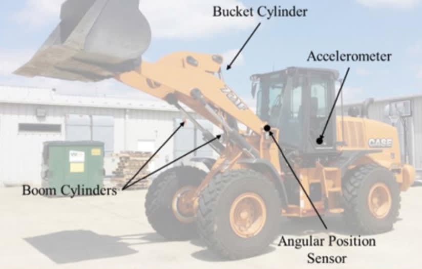
Researchers from Purdue University propose a concept for an active system to reduce machine oscillations based on a controller that identifies the frequencies of the oscillation to be damped. The researchers chose a 14-ton Case 721F wheel loader from CNH Industrial as the reference machine because they had available experimental data for the dynamic response of the hydraulic boom actuator as well as the performance of the commercial passive ride control (PRC) system for the machine.

The wheel loader was equipped with a traditional load-sensing hydraulic circuit, composed of three actuators, where two act in parallel to lift the boom and the third rotates the bucket. It also was outfitted with a National Instruments cRIO-9076 for data acquisition and control, an Analog Devices ADXL335 accelerometer from SparkFun, and ASM Sensors’ PRAS27 angular position sensor. The accelerometer (-3 g to 3 g range) was installed in the cabin under the operator’s seat, to record the acceleration in the center of mass of the chassis; the angular position sensor (0° to 180°) determines the instantaneous angular displacement of the boom.
The control methodology was implemented within the LabVIEW system design software. The controller was simulated using a four-degrees-of-freedom vehicle dynamic model of the machine developed within the research used as a plant model, and on realistic dynamic response of the hydraulic system. Simulation results confirmed the effectiveness of the proposed control strategy, demonstrating its potential application to earthmoving machines.
Passive vs. active ride control systems

Because vibrations are a perennial issue with earthmoving machines, quite a few different solutions have been proposed in the past. These solutions fall primarily into two different categories: passive and active. So-called “passive” ride control systems seek to use the properties of hydraulic systems to their advantage, but they can only do so at the expense of modifying the existing hydraulic circuit of the machine. These systems often incorporate capacitive or resistive elements into the circuitry, capable of conditioning the system response to cancel out vibrations that would otherwise be transmitted to the machine chassis. The use of additional resistances represents a commercially viable solution in load handling machines such as hydraulic cranes. Such control setups can be quite effective at oscillation reduction, but the additional circuitry can negatively affect the energy efficiency of normal machine operation.

In construction machines such as wheel loaders, instead it is quite common to use accumulators within the hydraulic lines connecting the boom actuators. When the PRC system is activated, the additional capacitance introduced by the accumulator permits the boom to oscillate, counteracting the oscillations at the machine chassis caused by driving on uneven ground. The extra cost of the hydraulic components is one drawback of PRC systems; another is that the systems can only be optimized for a specific operating condition. When the system is far from that design point, their effectiveness can be severely limited.
While passive systems modify the hydraulic setup of the system, “active” vibration reduction strategies can be applied using the standard hydraulic architecture to realize the same principle of counteracting the machine oscillations through proper motion of the main boom. They are called active because they utilize sensor data in real-time to actively generate a command signal which causes a motion that cancels out the system vibrations. These systems are documented in several patents, and their effectiveness to earthmoving machines in controlled environments has previously been demonstrated for displacement-controlled architectures of the hydraulic system.
Despite their promise, these active ride control (ARC) systems are not currently available in commercial machines. This is mainly because of the dynamic bandwidth limitation of the hydraulic components for mobile applications, as well as the difficulties related to the development of a suitable control strategy able of guaranteeing performance in all possible operating conditions.
The Purdue researchers pursued development of a proper control strategy for an ARC system. The ARC control algorithm needs to generate a suitable command signal based on the proper feedback sensor data. In general, investigations such as this tend to utilize more traditional control structures, like proportional-integral-derivative control. The researchers, however, pursued a more unconventional strategy, which takes advantage of the fact that the system under consideration oscillates at very specific frequencies.
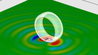
The vibrations occurring in earthmoving machines often have very particular characteristics. These are mechanical systems composed of massive components (chassis, boom and bucket, with possible load in it) linked with mostly rigid connections. Also, their tires act in many ways like spring-damper connections between the vehicle and the ground. Due to these considerations, earthmoving machines tend to exhibit very strong resonances at specific frequencies related to machine geometry and effects such as tire stiffness, etc.
Therefore, the controller uses frequency content information from the vibrations to determine the necessary frequencies for the periodic control signal that it generates. The control law used generates a periodic signal comprising multiple sinusoidal waveforms which are tuned to provide the maximum attenuation of system vibrations. A similar strategy has previously been applied with success to control vibrations in a stationary crane. To tune the controller parameters to their proper values, an optimization scheme can be used. This approach has previously seen success in vibration damping strategies.
For the proposed concept, a dynamic model of the machine was constructed, incorporating considerations for the free-body motion of the machine components, the behavior of the hydraulic systems used for controlling the motion of the machine actuator, and the impact of the pneumatic tires on the system dynamics.
Model validation and controller results

The model was validated considering two case studies, a step response of the machine and a case of controlled disturbances introduced by a speed bump installed at the Maha Fluid Power Research Center. In the first case study, a step input command in flow was given to the model, and the boom angular position and cab acceleration have been compared to experimental data.
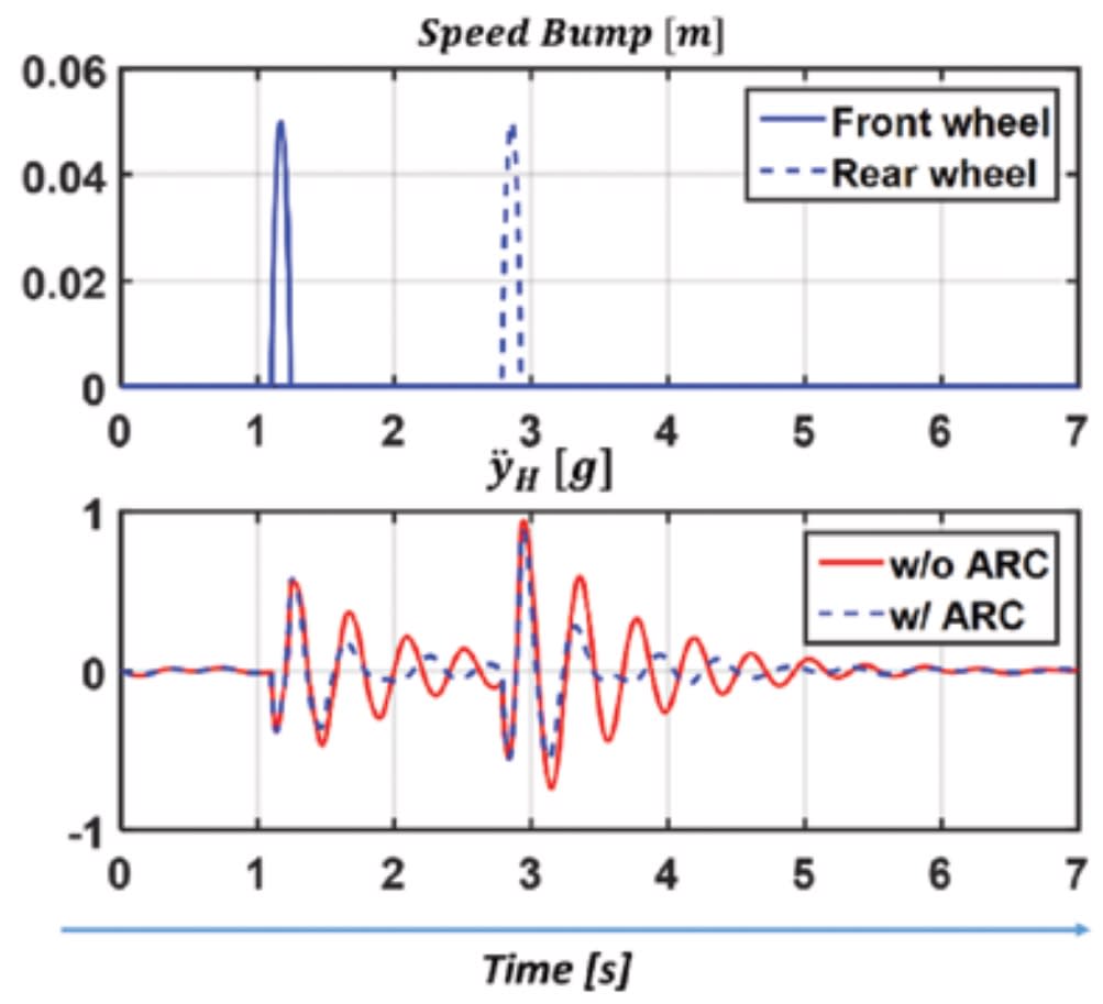
In the second case study, a disturbance input reflecting a speed bump was given to simulate the contact between a speed bump and the front wheels, and a similar disturbance input was given after a certain amount of time to reflect the vertical velocity of the rear wheels.
The results confirmed the model tracking capability of the experimental measurements. Although minor differences can be noticed, the model replicates the effects of the input command and the effects from input disturbances, which help to verify the results obtained where the controller has been applied. The difference between simulation and experimental results in the boom angular position are mainly due to underlying linear assumptions in the model.
To further validate the model, a representative input of a speed bump was developed. The distance from the input to the front wheel and the rear wheel is calculated as a function of the velocity of the machine, to reproduce the exact moment of impact.
The effectiveness of the proposed controller was evaluated on the model. Results were obtained from two different simulations: one in which the system travels over the speed bump and one in which it travels on uneven ground, where the road profile is consistently uneven to put more stress on the controller. The results from the speed bump simulation also were compared to the native PRC of the machine, testing the machine on the speed bump and comparing the results of the free oscillations and with the PRC activated, to compare the effectiveness of the experimental PRC and the simulated ARC.
The main results of the simulation study are summarized in the table. The PRC clearly shows better effectiveness than the proposed ARC, which suffers from the limited dynamics of the hydraulic system that controls the boom actuator. A faster dynamic of such system would bring the ARC performance more in line with the PRC. However, even by using the standard hydraulic components, the ARC shows considerable advantages with respect to complete absence of control. With that, the ARC represents a clear alternative to the more expensive PRC system. Moreover, the ARC offers the possibility of optimizing the parameters of the controller for different operating conditions, thus adapting to machine load, speed and ground contour, for example.
For the two considered conditions, the simulated effectiveness of the proposed control strategy justifies its further study — as future work — through the implementation on an electrohydraulic version of the reference machines.
This article is based on SAE Technical Paper 2016-01-8121 written by Riccardo Bianchi, Addison Alexander, and Andrea Vacca of Purdue University.
More From SAE Media Group
Sensor Technology
A Better Way to Measure Acceleration
Tech Briefs
Laser-Light-Based Accelerometer

Motion Design
Built-In Vibration Control to Soundproof Spaces

Motion Design
High-Sensitivity, Low-Noise MEMS Accelerometer
Motion Design
Multi-Axis Motion Controller Accelerates Gear Testing
Sensor Technology
Next-Generation MEMS IMUs — High Performance, Scalable

Sensor Technology
New Products
Tech Briefs
Disrupting the Automobile Design Process
Off-Highway Engineering
Digitalization of Product Engineering
Battery Technology
Using Multiphysics to Predict and Prevent EV Battery Fire
Tech Briefs
A Self-Powered Trailer

Battery Technology
An Immersive Solution for Thermally Safer EV Batteries
Tech Briefs
Vibration-Dampening Pedestal for MEMS
Tech Briefs
Device Detects Subatomic-Scale Motion
Automotive Engineering
BMW, Classiq Find Better Architectures Through Quantum Computing
Automotive Engineering
Reducing NVH Through Refined Powertrain Measurement
Sensor Technology
Energy Harvesting Can Enable 1 Trillion Battery-Free Sensors in the IoT
Tech Briefs
Periodic Wave Disc Brake Rotor

Tech Briefs
Q&A: Wireless Charging for Electric Vehicles
Motion Design
Precision Low-Speed Motor Controller
Tech Briefs
Tension Element Vibration Damping
Top Stories
INSIDERManufacturing & Prototyping
![]() How Airbus is Using w-DED to 3D Print Larger Titanium Airplane Parts
How Airbus is Using w-DED to 3D Print Larger Titanium Airplane Parts
INSIDERManned Systems
![]() FAA to Replace Aging Network of Ground-Based Radars
FAA to Replace Aging Network of Ground-Based Radars
NewsTransportation
![]() CES 2026: Bosch is Ready to Bring AI to Your (Likely ICE-powered) Vehicle
CES 2026: Bosch is Ready to Bring AI to Your (Likely ICE-powered) Vehicle
NewsSoftware
![]() Accelerating Down the Road to Autonomy
Accelerating Down the Road to Autonomy
EditorialDesign
![]() DarkSky One Wants to Make the World a Darker Place
DarkSky One Wants to Make the World a Darker Place
INSIDERMaterials
![]() Can This Self-Healing Composite Make Airplane and Spacecraft Components Last...
Can This Self-Healing Composite Make Airplane and Spacecraft Components Last...
Webcasts
Defense
![]() How Sift's Unified Observability Platform Accelerates Drone Innovation
How Sift's Unified Observability Platform Accelerates Drone Innovation
Automotive
![]() E/E Architecture Redefined: Building Smarter, Safer, and Scalable...
E/E Architecture Redefined: Building Smarter, Safer, and Scalable...
Power
![]() Hydrogen Engines Are Heating Up for Heavy Duty
Hydrogen Engines Are Heating Up for Heavy Duty
Electronics & Computers
![]() Advantages of Smart Power Distribution Unit Design for Automotive...
Advantages of Smart Power Distribution Unit Design for Automotive...
Unmanned Systems
![]() Quiet, Please: NVH Improvement Opportunities in the Early Design...
Quiet, Please: NVH Improvement Opportunities in the Early Design...