



Laser-Based System for Measuring and Analyzing Vibrations
Unlike accelerometers, noncontact sensors do not alter dynamics of lightweight objects.
A system for noncontact measurement and analysis of vibrations of an electronic circuit board or a similar lightweight, nominally flat, rectangular object has been developed. This system, which utilizes laser displacement sensors, offers an important advantage over a traditional vibration- measurement system that utilizes accelerometers mounted on the vibrating object under test: Accelerometers are not suitable for vibration testing of a lightweight object because they contribute mass to the object and thereby alter the dynamic behavior of the object and thereby, further, give rise to errors in vibration-test data. In contrast, the laser displacement sensors in the present noncontact system do not contribute mass and do not significantly alter the dynamics.

The system includes four laser displacement sensors (for the sake of simplicity, only two are shown in the figure). The sensors are positioned at a distance of ≈1 cm from the circuit board or other object under test, which is mounted on a shaker table to induce bending vibrations, which involve displacements perpendicular to the nominal plane of the object. The sensors are aimed at the object along axes perpendicular to the nominal plane of the object so as to measure the vibrational displacements perpendicular to the nominal plane of the object. The four sensors acquire displacement data simultaneously from four different positions along the horizontal dimension of the object. They can measure displacements of as much as ±1 mm.
The four sensors are mounted on a bracket that can be raised or lowered to enable acquisition of data at different vertical positions (eight different vertical positions in the original application). Thus, from measurements made at the four horizontal positions with the sensors at various increments of vertical position, it is possible to acquire data to characterize vibrations at an array of points that define a grid spanning the object [in the original application a grid of four horizontal increments of 0.7 in. (≈1.8 cm) and eight vertical increments of 0.4 in. (≈1 cm) spanning the circuit board].
In operation, the sensor readings are sampled at a rate of as much as 7.8 kHz as the shaker table is excited to produce sinusoidal vibrations that are swept through the vibrational-frequency range of interest (20 Hz to 2 kHz in the original application). The data thus acquired are processed by special- purpose software that yields information on the peak displacement and the resonance frequency of the first vibrational mode and generates a motion picture showing the displacement in this mode. In the original application, testing showed that the system captured the resonance frequency with an error of no more than 1.5 percent and the peak displacement with an error of no more than 0.7 percent.
This work was done by Krissa Elizabeth Arn of the Massachusetts Institute of Technology.
MIT-0001
This Brief includes a Technical Support Package (TSP).
Laser-Based System for Measuring and Analyzing Vibrations
(reference MIT-0001) is currently available for download from the TSP library.
Don't have an account?
More From SAE Media Group
Medical Design Briefs
Product Focus: Test & Measurement
Photonics & Imaging Technology
Compact MEMS-Based NIR Spectroscopy for Mobile Applications
Photonics & Imaging Technology
SPIE Photonics West 2022 Preview
Photonics & Imaging Technology
2021 OEM Photonics & Imaging Directory
Aerospace & Defense Tech Briefs
Streamlined Microcomb Design Provides Control With The Flip of a Switch
Photonics & Imaging Technology INSIDER
Tying Overlapping Laser Beams into Stable 'Optical Knots'
Photonics & Imaging Technology
Closing the Design-to-Manufacturing Gap for Optical Devices
Photonics & Imaging Technology
SPIE Photonics West 2023 Preview
Photonics & Imaging Technology
New Products
Tech Briefs
New Family of Glass for Lens Applications

Photonics Tech Briefs
Vibration Isolation in Optical Test Systems
Aerospace & Defense Tech Briefs
Designing COTS Optics Into Defense Projects
Photonics & Imaging Technology
Photonics West 2021 Preview
Tech Briefs
Beam Crossing Optical System

Motion Design
Laser-Light-Based Accelerometer
Defense INSIDER
Using Squeezed Light to Develop Sensors That Defy Defense Limits
Photonics & Imaging Technology
How a UV-Visible-NIR Range Microscope-Spectrometer Works
Photonics & Imaging Technology
Pratt & Whitney, Virginia Tech Pioneer Laser-Optical Approach for Turbofan Engine Thrust Measurement
Photonics & Imaging Technology
Measuring Blood Glucose Levels with Lasers
Photonics & Imaging Technology INSIDER
NIST Creates Strobe Light to Test 5G Resonators
Photonics & Imaging Technology INSIDER
New Product Launches and Technologies to See at Photonics West 2025

Tech Briefs
Passive Polarized Fiber Optic Sensing
Medical Design Briefs
Ultra-Sensitive Photoacoustic Microscopy Enables New Biomedical Applications

Tech Briefs
Compact Laser Source Detects Pollution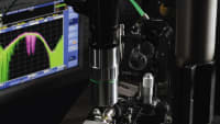
Overview
I apologize, but I cannot find relevant information in the provided pages to create a summary of the document titled "Design of a Non-Contact Vibration Measurement and Analysis System for Electronic Board Testing." However, based on my knowledge, I can provide a general overview of what such a document might cover.
The thesis likely discusses the development of a non-contact system designed to measure and analyze vibrations in electronic boards, which is crucial for ensuring the reliability and performance of electronic devices. The document may outline the challenges associated with traditional vibration measurement techniques, such as the need for physical contact, which can interfere with the operation of sensitive electronic components.
The author might present various methodologies for non-contact measurement, possibly including laser Doppler vibrometry or other optical techniques that allow for precise vibration analysis without direct contact. The thesis could detail the design process, including the selection of sensors, data acquisition systems, and analysis software.
Additionally, the document may include experimental results demonstrating the effectiveness of the proposed system in real-world applications, such as testing circuit boards under different operational conditions. The findings could highlight the advantages of non-contact methods, such as improved accuracy, reduced risk of damage to components, and the ability to measure vibrations in a wider range of scenarios.
The thesis would also likely discuss the implications of this research for the field of mechanical engineering and electronics, emphasizing how improved vibration measurement can lead to better product design, enhanced durability, and increased consumer safety.
In conclusion, while I cannot provide a specific summary from the document itself, the thesis likely represents a significant contribution to the field of vibration analysis in electronic testing, showcasing innovative solutions to common engineering challenges. If you have any specific questions or need further information, feel free to ask!
Top Stories
INSIDERDefense
 New Raytheon and Lockheed Martin Agreements Expand Missile Defense Production
NewsAutomotive
 Ford Announces 48-Volt Architecture for Future Electric Truck
INSIDERManufacturing & Prototyping
 Active Strake System Cuts Cruise Drag, Boosts Flight Efficiency
ArticlesTransportation
 Accelerating Down the Road to Autonomy
INSIDERMaterials
 How Airbus is Using w-DED to 3D Print Larger Titanium Airplane Parts
Road ReadyTransportation

Webcasts
Electronics & Computers
 Cooling a New Generation of Aerospace and Defense Embedded...
Power
 Battery Abuse Testing: Pushing to Failure
Connectivity
 A FREE Two-Day Event Dedicated to Connected Mobility
Automotive
 Quiet, Please: NVH Improvement Opportunities in the Early Design Cycle
Transportation
 Advantages of Smart Power Distribution Unit Design for Automotive &...
Aerospace
 Sesame Solar's Nanogrid Tech Promises Major Gains in Drone Endurance