


Aerodynamics and Flow Simulations Come of Age
With the advent of faster computers, engineers are using CFD software as a practical tool, shaping designs early in the product development cycle. The challenges today are in how best to use it and by whom.
"Adecade ago, we had to convince people that CFD and simulation had value. Nowadays CFD is a well-accepted tool in the automotive industry used in all phases of the vehicle development process,” said Dr. Burkhard Hupertz, Supervisor, Thermal & Aerodynamics System Engineering/ Computer Aided Engineering for Ford in an interview with Automotive Engineering. His team is responsible for the virtual optimization and verification of new vehicle designs in vehicle aerodynamics and powertrain cooling.
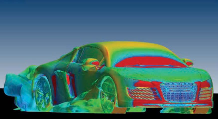
Universal use comes to a mature technology when results are trusted. “For understanding fundamental aero-dynamics and optimizing the exterior shape of a vehicle, as well as the underbody, the methodology is very mature,” he said. As a result, expectations of CAE in the development process have changed significantly. Once CAE was primarily used to assess the performance of a proposed design solution. “Today, CAE is expected to drive the vehicle development considering a continuously growing number of design parameters,” said Hupertz.
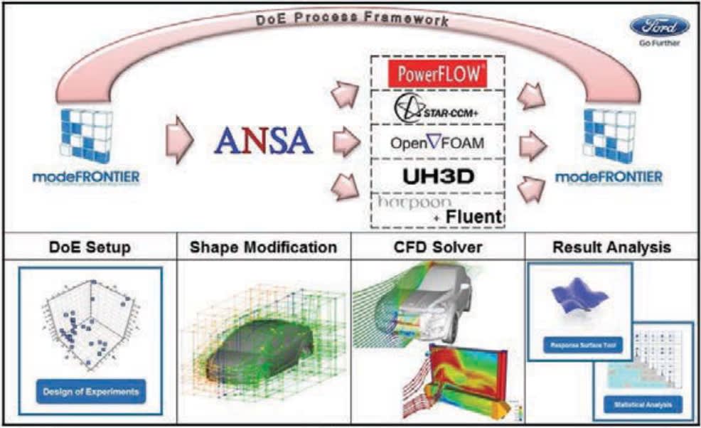
Toward that end, Ford is now identifying how best to use CFD to explore the most important and dependent parameters in an emerging vehicle design. Hupertz believes that CAE-based design of experiments (DOE) is the best solution. DOE allows them to explore the effect of a large number of design parameters on vehicle shape and system performance. Optimization software packages that carefully plan out the best use of hundreds of runs are key. Also key is a sophisticated morphing tool to help designers understand how they can best improve the vehicle shape. Finally, “we have put a lot of effort into friendly user interfaces so that designers and artists can understand and visualize what we aerodynamics engineers are talking about,” said Hupertz.
New vehicles, new worries
As CFD software simulation evolves, so does the market it serves, observed Frederick Ross, Director of Ground Transportation for CD-adapco. He notes that electric vehicles (EVs) and EV technology are now important design subjects. Energy use and management are paramount in EVs and hybrids of various sorts. Efficient aerodynamics design in such vehicles means reduced cooling drag, rolling resistance, form drag (Cd), and transmission losses, according to Ross: “As people attempt to squeeze out more fuel economy, it becomes a full-out effort in all these areas.”
In such analyses, systems simulations and interactions become important, rather than aerodynamics in isolation. He relates that in 2007, the company redesigned its STAR-CCM+ code to make it easier to analyze system simulations. “That is what is driving an optimum design; it is not only fluid flow,” explained Ross. STAR-CCM+ includes mechanical stress, heat transfer, and aero-acoustics among other physics domains. STAR-CCM+ features a coupled solver for multi-physics problems.
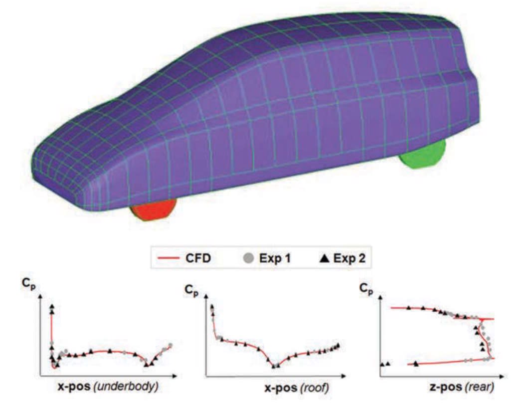
The development process itself is a coupled system of wind-tunnel testing and CFD simulations. “All major automakers today are using both simulation and wind tunnels on a daily basis for aerodynamics,” he said. Wind tunnels employ approximations just as much as with simulation — just different ones. Wind tunnels also produce results faster — once the prototypes and parts are fabricated. Simulation, on the other hand, allows testing of designs that may never be physically realized. It also allows for visualization of results simply not possible with physical data, he explained. “The two tools really complement each other.”
Ross also noted that his customers are asking for more optimization solutions to make their simulations maximally usable. The company recently purchased Red Cedar with a suite of products aimed at optimizing designs through its proprietary SHERPA algorithm.
In licensing, CD-adapco considers the needs of users who do not have constant demands for simulation with Power-On-Demand, enabling an unlimited number of cores per case. For optimization studies, clients typically run several jobs simultaneously, and for those cases Power Tokens enable users to run a single large case or multiple smaller jobs.
Complexity tamed with 21st century computing
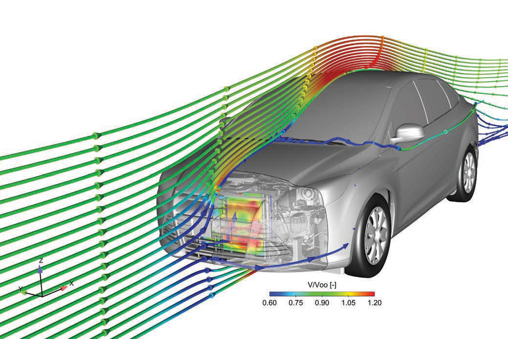
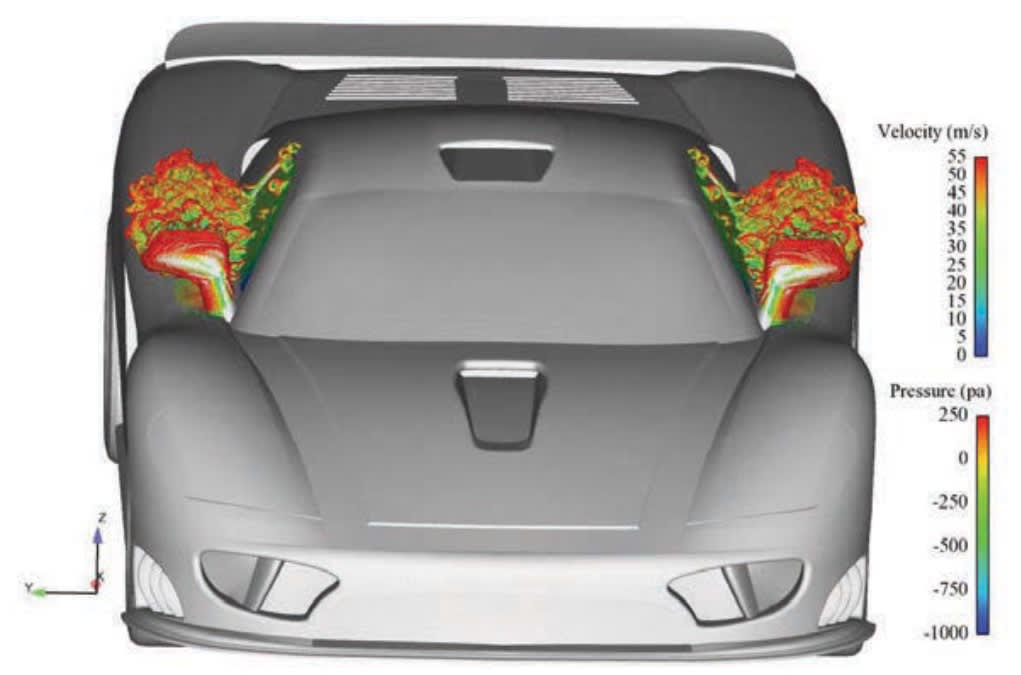
Mark Doroudian, Director of Engineering for ESI North America, believes that computing power available today has made high-fidelity CFD more practical. “For noise applications around a car, we use mesh element sizes of 1 to 2 mm near the region of interest, and these can be computed on Linux clusters for faster turnaround time,” he told Automotive Engineering. For simulating the flow structure around an entire vehicle, the mesh elements are as fine as 5 to 10 mm (0.2 to 0.4 in), resulting in models consisting of 80 million cells or more — again, easily handled with today’s computers.
For most vehicle-size problems, including exterior and underhood flow simulations, ESI uses the OpenFOAM software. It is an open-source CFD solver created by OpenCFD Ltd. and released by the OpenFOAM foundation. OpenFOAM uses a finite-volume approach primarily to solve the Navier-Stokes equations for fluid flow. Doroudian reports that automotive engineers use it for climate control, exterior aerodynamics, and aero-induced vibro-acoustics, as well as engine work, such as intake and exhaust manifold design and combustion modeling.
High-fidelity CFD simulations are practical because of the advent of parallel computing on multiple processors. Users are even calculating compute-intensive unsteady, or time-dependent, flow solutions. Since many licensing models are leased with payment proportional to the number of processors, large problems requiring hundreds of simultaneous processors can get expensive, according to Doroudian. “That is the advantage of the open-source OpenFOAM; since it is free you can calculate as large a problem as you wish. You can run thousands of processors with no added license expense,” he explained. OpenCFD is a wholly owned subsidiary of the ESI Group.
Workflow automation over advanced physics
Doroudian also reports that his automotive customers are — in general — requesting more help on workflow issues than requiring more advanced physics. “They want methodologies for doing things faster,” he explained. That means a series of steps starting with massaging a CAD model to get it “ready” for CAE. Then, the user needs to create a mesh and preprocess the model before running it. The final step is visualizing the results. He told Automotive Engineering that his customers express a partiality for open-source solutions, and so they offer the DAKOTA optimization toolbox. It, too, is an open-source code available from Sandia National Laboratory, which includes a number of methods for design optimization, parameter estimation, and sensitivity analysis.
Altair has taken a direct approach in improving workflow and turn-around for automotive aerodynamics with its HyperWorks Virtual Wind Tunnel (VWT) application, a streamlined workflow process for wind tunnel simulations. Announced in October 2013, VWT is based on Altair’s CFD solver AcuSolve and contains automatic meshing and reporting. “It includes some advanced physics, like rotating wheels, radiator modeling, and fluid-structure interactions,” explained Marc Ratzel, Director, CFD Solutions for the company, in an interview with Automotive Engineering. Users set up cases and boundary conditions through a scaled-down, minimalist GUI interface, and after calculation, the VWT publishes a PDF report. Wheels, spoilers, and radiators are selected for specific simulations with a mouse and visual model browser. The model input is a computational surface mesh defined in Nastran format.
The core of VWT is Altair’s AcuSolve CFD solver. Unlike many other CFD codes, it is based on a finite-element approach, rather than the more popular finite-volume technique. “Two key components contribute to its robustness: the Galerkin Least Square (GLS) finite-element formulation, and a novel iterative linear equation solver,” explained Ratzel. He believes this means AcuSolve is more accurate, more robust, and forgiving regarding distorted elements, which leads to shortening the time required to create a mesh. “It is also more computationally stable, making it easier to use and yielding shorter turnaround times as well,” remarked Ratzel. The VWT can also be coupled with the company’s HyperStudy software. HyperStudy allows user to explore, understand, and improve his or her system designs using methods such as DOE and optimization, according to the company.
Future enhancements Altair is looking to develop, according to Ratzel, include more integrated multiphysics simulations, acoustics inside vehicle cabins, and two-phase flow as well as further improved scalability, enabling parallel calculations over thousands of processor cores.
HyperWorks uses an on-demand licensing system. Unit-based with a pay-per-use model, according to a company spokesperson, it allows users across an organization to simultaneously access software without having to purchase seats or licenses.
Under the hood, too
It is also important to keep the system perspective. “While looking at a particular attribute such as fuel economy or emissions, regulations are important and you must balance all of the attributes that go into vehicle design, like drivability or passenger compartment comfort,” Ravi Shankar, Director of Simulation Product Marketing for Siemens PLM Software, told Automotive Engineering. “It does no good to look at these in isolation.” Toward that end, Siemens PLM Software has focused on building an integrated toolbox that ties together CAE simulation tools with its NX CAD software and its Teamcenter PDM platform. Users have access to proprietary tools, like NX Flow and NX Nastran, as well as popular third-party packages like LS-Dyna or Abaqus. Their focus is on workflow development, moving from CAD to a working analysis model as efficiently as possible.
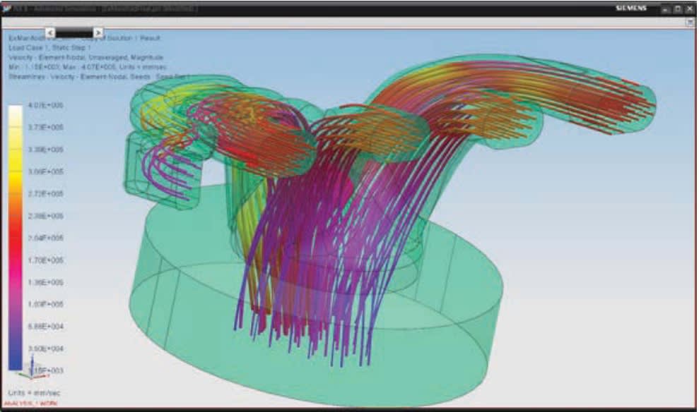
“NX Thermal/Flow includes domain decomposition techniques for solving large models along with a very cost-effective licensing scheme for parallel processing,” explained Shankar. “A single license of the add-on parallel processing module, together with the prerequisite core solver license, can be used to spawn a solver over as many processors as available.”
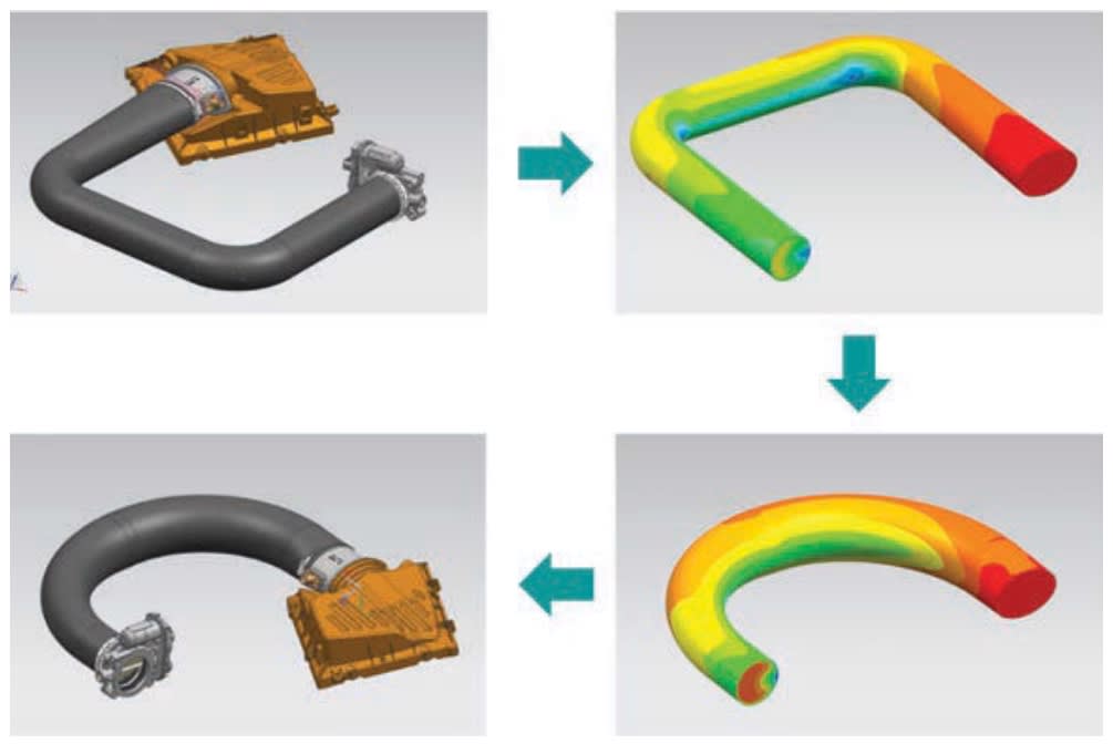
Shankar also related that many of the CFD applications his software supports are classic powertrain problems, such as optimizing underhood cooling or balancing exhaust and intake mani-fold flowfields, that require advanced surface mapping features to determine best-fit geometry.
One of those customers is General Motors in their Advanced Engine Design group. As Rod Baker, Design Technical Leader for GM, describes it, the integration of CAD and CAE is letting them put analytical tools directly in the hands of product designers. “This is new for us, and we found that the flow simulation is a very good tool to get [directional comparisons],” he explained. These product engineers use the tools to determine if a particular design is reasonable, if subsequent iterations are improving its performance, or if a change actually degraded performance and should be abandoned. “On a typical design, we might iterate a component’s shape 30 or 40 times,” he said, making it more efficient than involving a more highly specialized CAE analyst.
GM still employs such specialists in a separate CAE group, but templates have helped designers set up and run flow simulations. This greatly eases the use of CAE for flow simulations that guide early design choices. “We still go through an expert to verify confirmation runs,” explained Baker, “or to run coupled physics or more complex problems.” He also noted that the templates act more as an introductory tool for product designers to learn how to use the NX Flow simulations. “Once they have learned the tool, we find that they branch off and do their own setups as needed,” he said. The templates allow the product designers to evolve into users in their own right, putting aside the “training wheels” of the templates.
Another key point that Baker makes is that the optimization of geometry is entirely manual. Designers improve the geometry by reviewing the results of flow-field analysis and employing their own expertise and experience base to make the next change.
More From SAE Media Group
Aerospace INSIDER
Engineers Assess Flow Quality in Wind Tunnel Test Facility
Tech Briefs
Supersonic Spike Diffuser
Motion Design INSIDER
Nimble Dimples: Agile Underwater Vehicles Inspired by Golf Balls

Aerospace INSIDER
Accelerating Climate-Compatible Aircraft Design with AI
Automotive Engineering
Tesla Aerodynamicists Use CFD to Evaluate Yaw Performance

Aerospace & Defense Tech Briefs
SparkJet Actuators for Controlling Flows
Aerospace & Defense Tech Briefs
Application of CFD to a Slender-Bodied, Finned Projectile
Green Design & Manufacturing
How Terrain and Turbine Placement Affect Wind Energy Production

Off-Highway Engineering
Fan-Shroud Optimization for Enhanced Thermal Performance
Tech Briefs
Stretchable Mesh for Cavity Noise Reduction
Aerospace & Defense Tech Briefs
Comparing Blade-Element Momentum Modeling to 3-D CFD
Automotive Engineering
JLR’s Gaylard Offers Insights on Aerodynamics

Motion Control and Automation Technology INSIDER
Second, Smaller Rotor Increases Wind Turbine Efficiency
Aerospace INSIDER
Quarterhorse Hypersonic Test Aircraft Completes First Flight
Aerospace & Defense Tech Briefs
Boeing and NASA Unveil Lightweight, Ultra-Thin, More Aerodynamic Transonic Truss-Braced Wing Concept
Motion Design INSIDER
Computer Simulation Accurately Models Moving Cars
Tech Briefs
Robotic Wing Could Improve Drone Performance
Motion Design INSIDER
Feathered Robotic Wing Paves Way for Flapping Drones
Top Stories
NewsSensors/Data Acquisition
![]() Microvision Aquires Luminar, Plans Relationship Restoration, Multi-industry Push
Microvision Aquires Luminar, Plans Relationship Restoration, Multi-industry Push
INSIDERRF & Microwave Electronics
![]() A Next Generation Helmet System for Navy Pilots
A Next Generation Helmet System for Navy Pilots
INSIDERWeapons Systems
![]() New Raytheon and Lockheed Martin Agreements Expand Missile Defense Production
New Raytheon and Lockheed Martin Agreements Expand Missile Defense Production
NewsAutomotive
![]() Ford Announces 48-Volt Architecture for Future Electric Truck
Ford Announces 48-Volt Architecture for Future Electric Truck
INSIDERAerospace
![]() Active Strake System Cuts Cruise Drag, Boosts Flight Efficiency
Active Strake System Cuts Cruise Drag, Boosts Flight Efficiency
ArticlesTransportation
Webcasts
Aerospace
![]() Cooling a New Generation of Aerospace and Defense Embedded...
Cooling a New Generation of Aerospace and Defense Embedded...
Energy
![]() Battery Abuse Testing: Pushing to Failure
Battery Abuse Testing: Pushing to Failure
Power
![]() A FREE Two-Day Event Dedicated to Connected Mobility
A FREE Two-Day Event Dedicated to Connected Mobility
Automotive
![]() Quiet, Please: NVH Improvement Opportunities in the Early Design Cycle
Quiet, Please: NVH Improvement Opportunities in the Early Design Cycle
Electronics & Computers
![]() Advantages of Smart Power Distribution Unit Design for Automotive &...
Advantages of Smart Power Distribution Unit Design for Automotive &...
Unmanned Systems
![]() Sesame Solar's Nanogrid Tech Promises Major Gains in Drone Endurance
Sesame Solar's Nanogrid Tech Promises Major Gains in Drone Endurance