Manufacturer Reduces Risk and Improves Quality of Military Radar Receivers
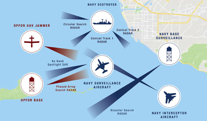
An industry-leading military radar receiver manufacturer needed to deliver radar receivers that met tough new customer specifications. To ensure a quality product, the manufacturer reviewed many aspects of its test strategy, focused on ensuring its radar receivers could meet the new specifications. Radar receiver sensitivity is critical for electronic warfare (EW) applications. A radar receiver that is outside specifications will fail to decipher signals properly from long distances. This is not an option in military applications.
Risk of False Passes
The aerospace and defense manufacturer needed to improve receiver sensitivity and the accuracy of its power level measurements in order to meet its design specifications and cost goals.
Receiver sensitivity is defined as the minimum signal level that is intelligible to the receiver or that can be demodulated effectively by the receiver. Sensitivity measurement accuracy relates directly to the power level accuracy of the low-level signal. An RF signal generator connected to the radar receiver antenna input generates the source signal used to determine receiver sensitivity. An RF signal generator with poor power level accuracy at very low power levels will cause inaccurate receiver sensitivity measurements.
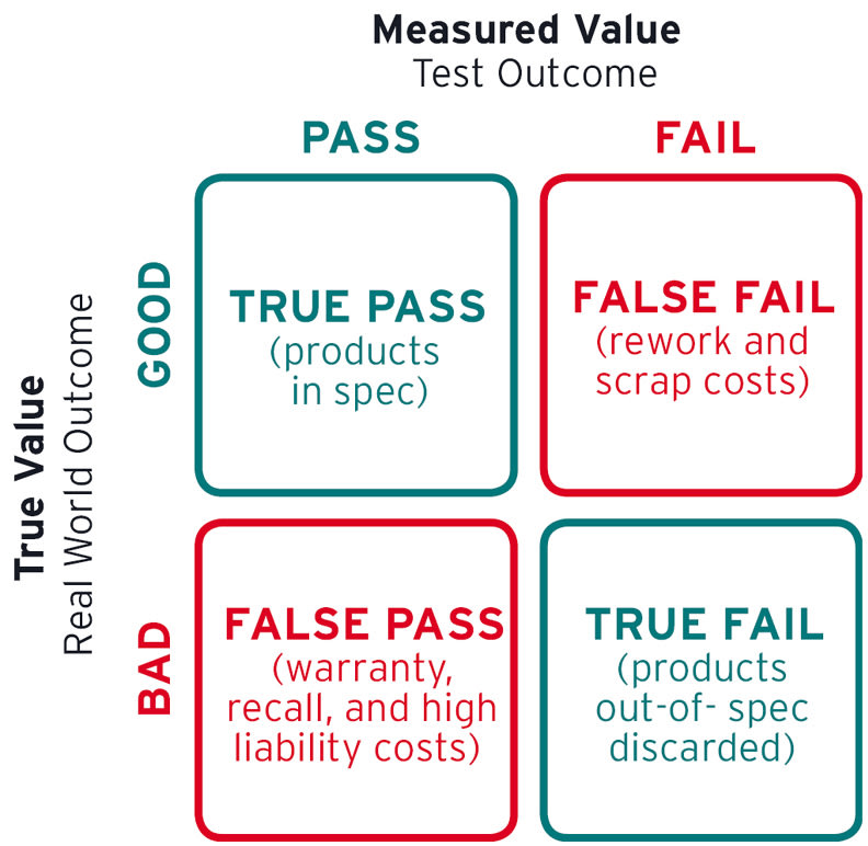
If the signal generator is out-of-specification, one of two measurement errors can occur. If the signal generator delivers a higher power level than indicated, the test may result in a false pass. The false pass results in the manufacturer shipping a product it believes meets customer receiver sensitivity requirements, when in fact, the actual sensitivity is several dB higher. Correspondingly, if the signal generator delivers an under-powered signal, a false fail occurs and a “good unit” is re-worked, resulting in waste and increased cost. False pass results put this aerospace and defense company at great risk (Figure 1).
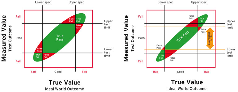
One method for reducing false pass results is to optimize test limits by using guardbanding. With measurement uncertainty (MU) data, guardbanded test limits can be set to reduce false passes. Figure 2 demonstrates how setting a tighter upper and lower test limit can reduce false passes.
Solution
Calibration ensures that test equipment performs to warranted specifications. Measurement uncertainty is a key contributor to false pass and false fail conditions. Reducing uncertainty starts with reviewing calibration data.
Keysight Technologies evaluated the customer’s most recent signal generator calibration report and discovered that the third-party calibration service provider only verified the power level accuracy of the signal generator at 0 dBm. The calibration did not meet the requirements for the customer’s specific application because the third party did not verify the lower power levels required for radar receiver testing. The much higher MU, as shown in Figure 3, meant the company was at significant risk of out-of-specification products passing quality assurance.
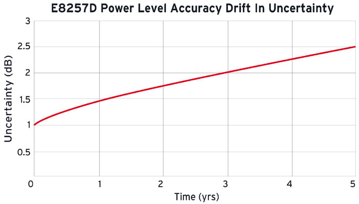
Keysight demonstrated a realistic level of drift for an uncalibrated power level parameter using a statistical model for random walk and known failure rates of the E8257D PSG signal generator. Figure 3 shows that the instrument drift for the power level accuracy of an E8257D — starting from the warranted specification of ±1.0 dBm — shifted to ±2.5 dB after five years. This large measurement uncertainty significantly increased the customer’s risk. Keysight shared a Keysight Calibration report for an E8257D at a test point at -90 dBm, proof that all factory test parameters perform within specification.
The ROI on Calibration
Keysight calculated the risk of reduced power measurement accuracy with the E8257D PSG analog signal generator. Two scenarios were modeled: one with a PSG calibrated with a very low MU and a second with a PSG that had drifted. The Keysight risk calculator used the mathematical equation for calculating risk as defined by the Joint Committee for Guides in Metrology (JCGM), a world-recognized organization formed by seven international organizations. The equation, which defines the four possible outcomes as false fail, false pass, true pass, and true fail, can be found at JCGM 106:2012 per section 9.5. 1
For modeling, the radar sensitivity for the test setup was identified at 10 GHz. A mean test value (customer specification) and guardband test limit were modeled at -88 dBm and -88.5 dBm, respectively. The MU for power level accuracy is only as good as its last calibration. After calibration, the MU for power level accuracy of an E8257A PSG analog signal generator is very small: <± 0.12 dB compared to that at <±2.5 dB with drift.
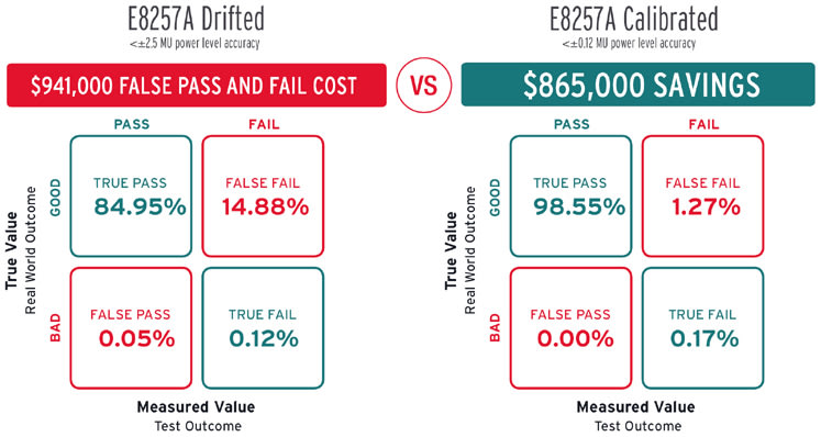
False passes dropped from 0.05% to <0.001%, representing a dramatic reduction in risk of shipping a defective or out-of-spec product. Keysight helped the customer estimate future cost avoidance of $865,000 as the result of reduced risk and cost of re-work. Improving measurement accuracy of a critical measurement parameter, such as power level accuracy, dramatically reduces risk and cost as shown in Figure 4.
Results
This radar receiver manufacturer had never seen a risk calculator based on JCGM’s mathematical definition of risk used to quantify business results in monetary terms. The before and after comparisons of lowering the measurement uncertainty of a critical power level accuracy specification convinced the manufacturer to take action.
This identified a gap in the method of calibration that low power accuracy was not measured. The discovery enabled them to reduce risk and costs by changing existing processes and provided a realistic estimate of savings.
This article was contributed by Keysight Technologies, Santa Rosa, CA. For more information, visit here .
Reference
- BIPM (Bureau International des Poids et Mesures), GUM: Guide to the Expression of Uncertainty in Measurements.
Top Stories
INSIDERRF & Microwave Electronics
![]() FAA to Replace Aging Network of Ground-Based Radars
FAA to Replace Aging Network of Ground-Based Radars
PodcastsDefense
![]() A New Additive Manufacturing Accelerator for the U.S. Navy in Guam
A New Additive Manufacturing Accelerator for the U.S. Navy in Guam
NewsSoftware
![]() Rewriting the Engineer’s Playbook: What OEMs Must Do to Spin the AI Flywheel
Rewriting the Engineer’s Playbook: What OEMs Must Do to Spin the AI Flywheel
Road ReadyPower
![]() 2026 Toyota RAV4 Review: All Hybrid, All the Time
2026 Toyota RAV4 Review: All Hybrid, All the Time
INSIDERDefense
![]() F-22 Pilot Controls Drone With Tablet
F-22 Pilot Controls Drone With Tablet
INSIDERRF & Microwave Electronics
![]() L3Harris Starts Low Rate Production Of New F-16 Viper Shield
L3Harris Starts Low Rate Production Of New F-16 Viper Shield
Webcasts
Energy
![]() Hydrogen Engines Are Heating Up for Heavy Duty
Hydrogen Engines Are Heating Up for Heavy Duty
Energy
![]() SAE Automotive Podcast: Solid-State Batteries
SAE Automotive Podcast: Solid-State Batteries
Power
![]() SAE Automotive Engineering Podcast: Additive Manufacturing
SAE Automotive Engineering Podcast: Additive Manufacturing
Aerospace
![]() A New Approach to Manufacturing Machine Connectivity for the Air Force
A New Approach to Manufacturing Machine Connectivity for the Air Force
Software
![]() Optimizing Production Processes with the Virtual Twin
Optimizing Production Processes with the Virtual Twin


