Using Electromagnetic Brakes to Keep Thrust Reversers IN PLACE
Applying reverse thrust redirecting engine power to oppose the direction of travel is a standard technique for decelerating aircraft after touchdown. The approach saves wear on the brakes of the landing gear wheels and reduces stopping distance. Although accidental deployment of the thrust reverser cowl could and did happen, it was assumed for decades that this would only present a hazard in the moments around takeoff and landing. With changes to engine design and aircraft aerodynamics, this assumption no longer held, as demonstrated by the catastrophic loss of Lauda Air Flight 004.

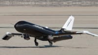
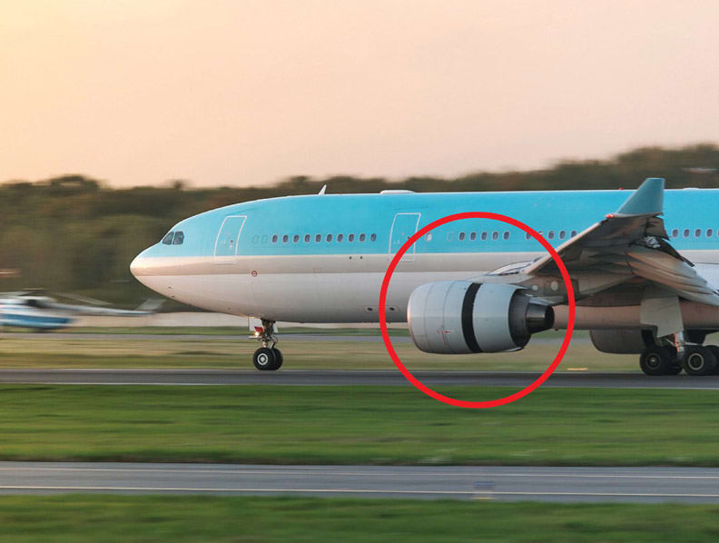
Early thrust reversers repositioned a portion of the engine cowling to literally redirect the force in the reverse direction. More recent designs move a portion of the engine cowling (the reverser sleeve) aft and use fans to redirect thrust at a shallower angle through the gap that opens up (Figure 1). For safety, this thrust reverser sleeve must be protected against unintended motion both when it is stowed and when it is fully deployed. As with all safety-critical tasks, these systems need redundancy. Spring-actuated, power-off electromagnetic locks (brakes) are a standard backup solution for this task. Because this type of electromagnetic brake is a mechanically actuated poweroff device, the cowling cannot move unless the lock is released by an electrical signal.
Particularly in the case of a safety system, proper choice of lock/brake technology is essential. Design teams need to understand the technologies and trade-offs involved in order to optimize system performance.
The Air Up There
The thrust reverser actuator and associated equipment are exposed to punishing conditions that make the industrial environment look benign. The units are located between the engine and the cowling. As a result, they need to survive repeated temperature cycling from -55°C to +115°C, or more, sometimes in a short period of time. Components are subjected to ongoing vibration and also shock loads. Contamination is always a factor, including deicing fluids, oils, solvents, dust, water, and salt air. Units are typically sealed for ingress protection but must be robust enough to survive if the seals fail.
All of these factors need to be considered in the context of the operating lifetime of a typical aircraft, which can run to multiple decades.
The Basics of Electromagnetic Brakes
In an electromagnetic brake, a fixed field coil acts as an electromagnet to control the position of an armature so that it either engages or disengages with a structure to generate holding/braking torque. Electromagnetic brakes are available in power-on and power-off designs. In a power-on brake, the brake is only engaged when current flows in the field coil. In a power-off brake, the brake remains engaged at all times unless the current is flowing in the electromagnet. Because an electromagnetic brake in a thrust reverser is designed to maintain the thrust-reverser sleeve in a stowed position during flight, a power-off design is the appropriate option.

The field coil of an electromagnetic power-off brake either attracts or releases the armature. These brakes need another technology to cause the armature to engage with the structure that generates holding/braking torque. The most appropriate approach is a spring-engaged, power-off brake.
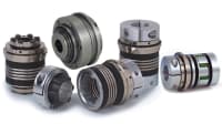
In the spring-engaged, power-off electromagnetic brake, a spring presses the armature into contact with the torque-producing structure of the output plate when the brake is in the power-off condition (Figure 2). When current runs through the field coil, the attraction between the magnetic field and the armature overcomes the spring force and the armature disengages from the torque-producing structure.
Spring-engaged brakes are economical and compact. They can be easily disengaged for maintenance using a manual release, which reduces cost of ownership over the lifetime of the equipment. Perhaps most important for this application, when a spring-engaged brake fails, it fails closed, or in the engaged position.
Electromagnetic brakes also can be engaged using magnets, but these designs are not appropriate for use in thrust reversers. Permanent magnets can demagnetize at high temperatures. They are vulnerable to corrosion, which can significantly reduce torque. When they fail, they can fail in the open position, which makes them hazardous for this application.
The spring and the field coil cause the armature to engage or disengage with the output plate, respectively. It is the output plate that generates the stopping/holding torque of the brake upon contact with the armature. That interface is responsible for the nuances of brake performance. For thrust-reverser applications, friction disks provide the best solutions (Figure 3).

In a friction brake, the armature presses against the surface of the friction disc, exerting holding or braking torque. The friction disc consists of a metal substrate with a friction coating applied to it. Friction brakes are suitable for dynamic engagement and can be used at high speeds to stop a runaway load without damage.
Some electromagnetic brakes use meshing teeth between the armature and the output plate to generate torque. Although tooth brakes offer a number of degrees of design freedom in terms of how the tooth profile affects the engagement and holding properties of the brake, a tooth brake should never be used in a thrust-reverser application. The components involved move at 20,000 RPM. Trying to engage the teeth at that speed would cause catastrophic failure.
Specifying the Right Electromagnetic Brake
Although the basic type of electromagnetic brake that should be used in a thrust-reverser application is limited, design teams have many degrees of freedom they can use to customize a brake for their particular needs. The process starts with gathering detailed information about the functional requirements and environment of the application (see table). The most important parameter for a brake, of course, is the torque. This includes the torque required to maintain the load (static torque) and stop a moving load (dynamic torque). In the moments of starting and stopping, the armature also generates drag torque that should be taken into account. Other essential parameters include response time, RPM, and duty cycle.
Structure
When it comes to torque, engineers have a number of parameters they can modify to get the optimal result for each specific case. Torque is a function of coefficient of friction, normal force, and radius/diameter of the disc. Although increasing the contact diameter will boost torque, the envelope dimension for the application is limited; remember, the assembly has to fit between the engine and the cowling. One way to increase torque without widening the diameter is to use multiple friction discs. Adding discs does increase length by a relatively small amount, but in general the application is more sensitive to diameter, which remains the same for a multi-disc design as for a single-disc design.

In theory, the number of discs that can be used is unlimited. In reality, beyond three discs, the drag torque generated begins to negatively impact overall performance.
Friction Material
Another way to increase torque is to choose a friction-disc material with a higher coefficient of friction. This approach can increase torque while maintaining or even reducing diameter and weight. The latter is a particularly important consideration in aviation applications. Every ounce that gets lifted off the ground increases fuel consumption. Even if the effect is small, it can total to a considerable increase in cost of ownership over 20 years of operation. Although specialty or custom friction coatings can be more expensive than standard versions, the extra expenditure may be more than justified by fuel savings over the lifetime of the equipment.
As always, there are trade-offs. If it is a custom material, it will need to be qualified for the environment. It has to stand up to the temperature extremes and exposure to moisture and contamination. In particular, the friction material must provide sufficient torque even when coated with oil from the engine. Friction discs also need to be rated to survive dynamic engagements.
Power Supply
An aircraft is a closed system so the brake needs to operate on the available voltages, typically 16 to 32 V. Current is the most important parameter as far as brake design and operation go. The wiring of the aircraft will typically impose an upper bound on current, so the brake needs to be designed to operate within those limitations. Remember that resistance increases as a function of temperature, which will have an effect on current.
System-Level Considerations
Although the technology platform is well-established, this type of brake is not a commodity item. It is a complex assembly with a number of degrees of design freedom. By making trade-offs, it is possible to balance performance with considerations such as size and cost. The result will be a better solution that most effectively supports the larger mission. This can only take place if the brake is considered early in the process.
As an aviation subsystem, an electromagnetic brake used in a thrust-reverser assembly has to pass stringent analysis, acceptance testing, and qualification. The components are subject to a number of standards, including DO-160, “Environmental Conditions and Test Procedures for Airborne Equipment,” from the RTCA. This needs to be considered at the component level and throughout development.
Taking into account all of the requirements of the application, a power off, spring-engaged electromagnetic friction brake is the most appropriate technology for a thrust reverser backup system. Knowing the right platform is just the start. Choosing the optimal brake requires careful analysis of all operating parameters to ensure an effective, reliable, and durable solution. For best results, start early and work closely with the vendor. The total solution will be the best possible fit for the aircraft, the application, and the project as a whole.
This article was written by Rocco Dragone, Senior Sales/Application Engineer, SEPAC (Elmira, NY). For more information, visit here .
Top Stories
INSIDERRF & Microwave Electronics
![]() FAA to Replace Aging Network of Ground-Based Radars
FAA to Replace Aging Network of Ground-Based Radars
PodcastsDefense
![]() A New Additive Manufacturing Accelerator for the U.S. Navy in Guam
A New Additive Manufacturing Accelerator for the U.S. Navy in Guam
NewsSoftware
![]() Rewriting the Engineer’s Playbook: What OEMs Must Do to Spin the AI Flywheel
Rewriting the Engineer’s Playbook: What OEMs Must Do to Spin the AI Flywheel
Road ReadyPower
![]() 2026 Toyota RAV4 Review: All Hybrid, All the Time
2026 Toyota RAV4 Review: All Hybrid, All the Time
INSIDERDefense
![]() F-22 Pilot Controls Drone With Tablet
F-22 Pilot Controls Drone With Tablet
INSIDERRF & Microwave Electronics
![]() L3Harris Starts Low Rate Production Of New F-16 Viper Shield
L3Harris Starts Low Rate Production Of New F-16 Viper Shield
Webcasts
Automotive
![]() Hydrogen Engines Are Heating Up for Heavy Duty
Hydrogen Engines Are Heating Up for Heavy Duty
Power
![]() SAE Automotive Podcast: Solid-State Batteries
SAE Automotive Podcast: Solid-State Batteries
Energy
![]() SAE Automotive Engineering Podcast: Additive Manufacturing
SAE Automotive Engineering Podcast: Additive Manufacturing
Manufacturing & Prototyping
![]() A New Approach to Manufacturing Machine Connectivity for the Air Force
A New Approach to Manufacturing Machine Connectivity for the Air Force
Software
![]() Optimizing Production Processes with the Virtual Twin
Optimizing Production Processes with the Virtual Twin

