


Non-Contact Circuit for Real-Time Electric and Magnetic Field Measurements
Sensor can measure electric and magnetic fields simultaneously.
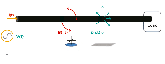
An energized electric power cable generates low-frequency electric and magnetic fields that are related to the voltages and currents. Especially at wavelengths λ>>d, where d is the distance away from an energized conductor and λ is the signal wavelength, we can extract electrical information with quasi-static near-field electric and magnetic field theory and the Principle of Superposition.
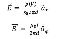
Coulomb’s and Biot-Savart Laws, respectively, relate the electric and magnetic fields to the voltage V and current I on a single straight energized wire (See Figure 1) where μ0 and ε0 are magnetic permeability and electric permittivity constants, ρ is the surface charge density on the wire, and aφ and ar are vectors pointing in the direction of the field in cylindrical coordinates. Superposition principles are used with Coulomb and Biot-Savart Laws in multi-wire configurations (i.e., 3-phase power cables). The boundary element method or electromagnetic models are typically used to solve for ρ(V), which changes minimally along the length of the wire at quasi-static frequencies.
There are many commercial-off-the-shelf (COTS) and Government-off-the-shelf (GOTS) sensors for making noncontact electric- and magnetic-field measurements. The electric-field (Efield) sensing team at ARL has previously characterized several E-field sensors, including SAIC Steered-Electron Electric-Field (SEEF) sensor, Srico optical sensor, Plessey EPIC sensors, QUASAR non-contact capacitive “dime” sensors, QFS 3-axis low-frequency (LF) E-field sensors, and the University North Carolina Charlotte (UNCC) custom E-field sensor. These sensors have produced good results, but do not include real-time programming abilities for signal conditioning. Furthermore there are no COTS or GOTS 1-Wire compatible electric- and magnetic-field sensors. Therefore, there is a need for integrated multimodal (electric- and magnetic-field) programmable sensors that are specifically designed for sensing the fields near energized cables. ARL’s multimodal D-dot (MD-dot) sensor addresses these needs, and additionally has “smart” features that adjust integrated circuits (ICs) on the sensor during start-up based upon the electrical characteristics of the attached cable.
The circuit’s primary design consists of a microcontroller, 8-channel digital-to-analog converter (DAC), variable gain chips, differential operational amplifiers, and E-field and B-field sensors. These components work together to form an interface that allows both onboard and external programming of the sensor, all while measuring electric and magnetic fields. Their connections are summarized in the block diagram.
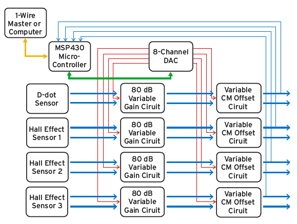
The circuit works in the following manner to set its own gain voltage and offset voltage, resulting in optimized output signal characteristics:
- Microcontroller reads ferroelectric random-access memory (FRAM) for current DAC output on 1 of its 8 channels.
- Microcontroller changes digital value for 1 of 8 DAC channels by serial peripheral interface (SPI) protocol (green).
- DAC sets corresponding analog output voltage to desired variable circuit input (red).
- Variable gain and/or variable offset stage outputs reflect changes (thick blue).
- Output signal is measured by microcontroller’s analog-to-digital converters (ADCs) (thin blue).
- Microcontroller increases or decreases (repeat 1–5) DAC setting, or keeps DAC setting based on ADC measurement and stores in FRAM.
The magnetic field is measured by MLX91205 Hall effect sensors. Three 1-dimensional Hall effect sensors were arranged in a line across an energized power cable to measure the magnetic field at 3 spatially diverse locations. These sensors can give an accurate measurement of a +/–10 mT magnetic field in the azimuthal direction. The MLX91205 output voltage is linear with magnetic-field strength up to a maximum chip output of 50-mV amplitude; therefore, the magnetic sensitivity Ω for the sensor can be computed.
This work was done by Sean M Heintzelman for the Army Research Laboratory. ARL-0195
This Brief includes a Technical Support Package (TSP).
Non-Contact Circuit for Real-Time Electric and Magnetic Field Measurements
(reference ARL-0195) is currently available for download from the TSP library.
Don't have an account?
More From SAE Media Group
Tech Briefs
Smart Sensor Technology for the IoT
Aerospace & Defense Tech Briefs
Ka-Band Front-End Monolithic Microwave Integrated Circuits (MMICs) and Transmit/Receive (T/R) Modules Testing
Aerospace & Defense Tech Briefs
New Pulse Analysis Techniques for Radar and EW
Aerospace & Defense Tech Briefs
Tips for Reducing Error When Using Eddy Current Measuring Techniques
Aerospace & Defense Tech Briefs
New Products
Aerospace & Defense Tech Briefs
VPT Rad-Hard Point of Load Converters Designed for Digital Processing in Space Environments
Aerospace & Defense Tech Briefs
Streamlined Microcomb Design Provides Control With The Flip of a Switch
Aerospace & Defense Tech Briefs
Hydraulic Cylinder Position Sensor Technology

Aerospace & Defense Tech Briefs
Robust Quantum Sensors Program
Aerospace & Defense Tech Briefs
Industry Invited to Participate in AeroTech Aerospace and Defense Technical Program
Aerospace & Defense Tech Briefs
Broadband 1.2- and 2.4-mm Gallium Nitride (GaN) Power Amplifier Designs
Aerospace & Defense Tech Briefs
Advances in Millimeter-Wave Isolator Design Launch Manufacturers into Stratospheric Operating Frequencies
Aerospace & Defense Tech Briefs
RF FPGAs for Multi-Function Systems
Aerospace & Defense Tech Briefs
Using High Bandwidth Oscilloscopes to Analyze Radar and Electronic Warfare Systems
Aerospace & Defense Tech Briefs
Understanding the “Black Art” of RF and Microwave Switching
Aerospace & Defense Tech Briefs
Quality Management Experts Provide Guidance on AS9100 Standard, Equipment Calibration
Aerospace & Defense Tech Briefs
Damping Measurement for Wafer-Level Packaged MEMS Acceleration Sensors
Aerospace & Defense Tech Briefs
Power-Line UAV Modeling and Simulation
Aerospace & Defense Tech Briefs
Thermal Conductivity Measurement Setup for Low-Temperature Characterization of Laser Materials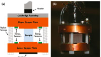
Tech Briefs
Crew Activity Analyzer
Aerospace & Defense Tech Briefs
90° Hybrid Coupled Power Amplifier – Pros and Cons
Tech Briefs
Radiation-Hardened Gain Digitizer
Aerospace & Defense Tech Briefs
Enhancing Mission Readiness with Rugged Portable Instruments
Off-Highway Engineering
Addressing Electromagnetic Compatibility in the Context of Aircraft Electrification
Aerospace & Defense Tech Briefs
Ruggedizing Coaxial and Fiber Optic Cable Assemblies from Mechanical Strain
Tech Briefs
High-Reliability Radio Frequency MEMS Switch
Aerospace & Defense Tech Briefs
A Focal Plane Array and Electronics Model for CMOS and CCD Sensors in the AFIT Sensor and Scene Emulation Tool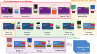
Aerospace & Defense Tech Briefs
Avoiding EMI
Aerospace & Defense Tech Briefs
CompactPCI Serial Space
Overview
The document titled "Non-Contact Circuit for Real-Time Electric and Magnetic Field Measurements," authored by Sean M. Heintzelman and published by the US Army Research Laboratory, presents a comprehensive study on innovative techniques for measuring electric and magnetic fields without direct contact. The report, finalized in October 2015, covers research conducted between March and August 2015.
The introduction outlines the significance of non-contact measurement methods in various applications, particularly in military and research settings where traditional contact methods may be impractical or hazardous. The report emphasizes the need for accurate, real-time measurements to enhance operational effectiveness and safety.
The methods and procedures section details the design and implementation of the non-contact circuit, including the use of advanced sensors. Key components discussed include the variable gain and offset stage, which is crucial for optimizing signal quality, and the integration of embedded systems that facilitate data processing and transmission. The report also covers 1-Wire interfacing, a communication protocol that allows for efficient data exchange between the sensors and the processing unit.
Results and discussion sections provide an in-depth analysis of the circuit's performance. The characterization of variable gain and offset is explored, highlighting how these adjustments improve measurement accuracy. The report also addresses digital noise and its impact on measurements, alongside an examination of the frequency response and field-referred noise spectral density, which are critical for understanding the circuit's operational limits.
Conclusions drawn from the findings emphasize the effectiveness of the non-contact circuit in providing reliable measurements of electric and magnetic fields. The report suggests that these advancements could lead to significant improvements in various applications, including military operations, environmental monitoring, and industrial processes.
The document includes a list of references and symbols, abbreviations, and acronyms used throughout the report, ensuring clarity and aiding in the understanding of the technical content. Acknowledgments are made to contributors who provided design and hardware support, underscoring the collaborative nature of the research.
Overall, this report represents a significant contribution to the field of electromagnetic measurement technology, showcasing the potential for non-contact methods to enhance data collection and analysis in real-time scenarios.
Top Stories
INSIDERWearables
![]() A Next Generation Helmet System for Navy Pilots
A Next Generation Helmet System for Navy Pilots
INSIDERWeapons Systems
![]() New Raytheon and Lockheed Martin Agreements Expand Missile Defense Production
New Raytheon and Lockheed Martin Agreements Expand Missile Defense Production
NewsAutomotive
![]() Ford Announces 48-Volt Architecture for Future Electric Truck
Ford Announces 48-Volt Architecture for Future Electric Truck
INSIDERAerospace
![]() Active Strake System Cuts Cruise Drag, Boosts Flight Efficiency
Active Strake System Cuts Cruise Drag, Boosts Flight Efficiency
ArticlesTransportation
![]() Accelerating Down the Road to Autonomy
Accelerating Down the Road to Autonomy
NewsUnmanned Systems
![]() Microvision Aquires Luminar, Plans Relationship Restoration, Multi-industry Push
Microvision Aquires Luminar, Plans Relationship Restoration, Multi-industry Push
Webcasts
Electronics & Computers
![]() Cooling a New Generation of Aerospace and Defense Embedded...
Cooling a New Generation of Aerospace and Defense Embedded...
Power
![]() Battery Abuse Testing: Pushing to Failure
Battery Abuse Testing: Pushing to Failure
Communications
![]() A FREE Two-Day Event Dedicated to Connected Mobility
A FREE Two-Day Event Dedicated to Connected Mobility
Unmanned Systems
![]() Quiet, Please: NVH Improvement Opportunities in the Early Design Cycle
Quiet, Please: NVH Improvement Opportunities in the Early Design Cycle
Transportation
![]() Advantages of Smart Power Distribution Unit Design for Automotive &...
Advantages of Smart Power Distribution Unit Design for Automotive &...
Aerospace
![]() Sesame Solar's Nanogrid Tech Promises Major Gains in Drone Endurance
Sesame Solar's Nanogrid Tech Promises Major Gains in Drone Endurance