


Damping Out Booming Noise
NVH improvement techniques are gaining traction with the goal to improve the quality perception of off-highway equipment performance and operator comfort.

As NVH gains importance in the quality of off-highway machine performance and operator comfort, it is essential to understand every aspect of the machine noise and its annoyance effect on the operator, then reduce the noise to a level that does not affect comfort and performance. Booming noise — a low-frequency NVH phenomenon below 200 Hz often described as a continuous bass drum roll, distant thunder sound, or a deep resonant sound like an explosion — is a major concern in off-highway machines.

The booming noise in off-highway machines can be caused by a combination of factors: the low natural frequencies and damping of the large panels of machine cabs; the low acoustic modes of the cab cavity; low-frequency excitation into the cab from machine noise sources such as engine, exhaust, cooling fan, etc.; and low frequency excitation to the machines from machine work tools and ground interaction inputs (tire lug, road profile, etc.).
Among the above potential factors, the low natural frequencies of the large panels are a big concern due to the off-highway machine size and its large un-subdivided panels. The forces from the machine work tools and the ground interactions can easily excite these large panels to resonate at their natural frequencies and cause a very unpleasant booming sound in the cab.
Due to the low-frequency characteristics of the booming noise, it is difficult to absorb the energy once it is generated in the machine cab. The best way to deal with booming noise is to prevent the noise from being radiated.
One approach is to shift the panels’ natural mode frequency if the excitation frequency is fixed. Other approaches include excitation source removal and damping application to lower or eliminate the resonance amplitude if the excitation frequency changes with machine working conditions. Recently, the booming noise in a cab was identified by researchers from Caterpillar using very simple but effective operational deflation shapes (ODS) and the application of a tuned mass damper (TMD) to suppress the resonance and improve the booming noise.
Source identification

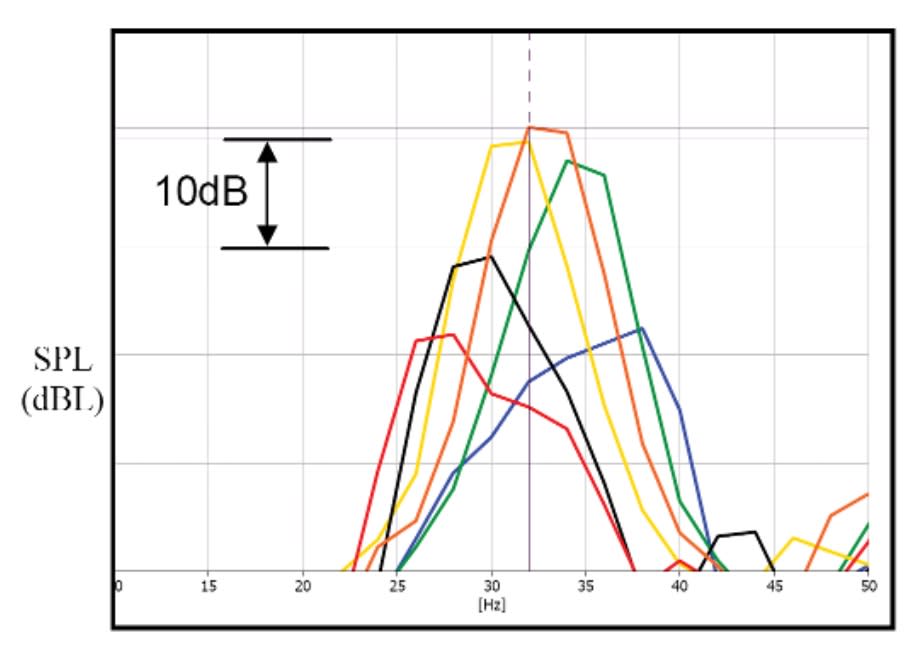
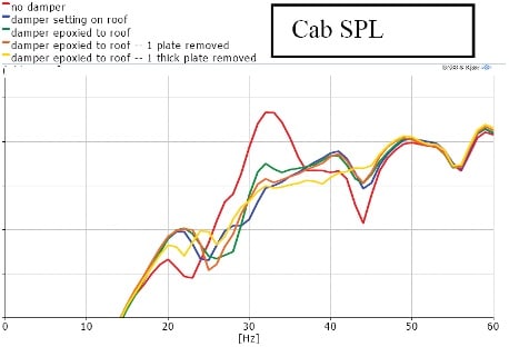
Past NVH tests of an off-highway machine showed large sound peaks in the 30- to 35-Hz range. Even though it does not affect the overall machine sound pressure level (SPL) in the cab after A-weighting, it is a concern that it may cause operator discomfort as a sound quality issue.
The SPL increases when the machine speeds increase and reaches its maximum at around 32 Hz; it dies down when the machine achieves higher speeds. This phenomenon indicates that the machine-ground interaction at tire lug pass frequency is the source of excitation, while some structures also have natural modes at 30- 35 Hz. Subjective operator evaluations carried out for this purpose verified that the booming is only noticed when the machine passes certain speeds. Once the machine speed is higher, the booming fades.
Because the tire lug pass was identified as the booming source, it is difficult to solve the problem addressing the source. It is impossible to get another tire that has significantly different tire lug so that the machine tire lug pass frequency either passes 30 Hz when the machine is at very low speed where the excitation force is very low, or does not reach 30 Hz in the normal machine working or traveling speeds.
With the booming noise excitation source excluded as a solution, other possible solutions would be working on the panels that resonate with the tire lug pass frequency. This requires the resonating panels be identified.
Panel sessions

To verify if and which cab panels are at play, experimental modal analysis (EMA) can be performed to identify the panels. Alternatively, one can do this virtually if a finite element (FE) model is available and validated.
Another quick way of doing that is to run ODS of the cab panels. The goal of ODS is to find out the real-world forced deflection of a structure during operation by measuring relative motion between one reference transducer and a group of other transducers on the structure. Note that if one does not have enough knowledge regarding the system being tested, sufficient measurement resolution should always be utilized to adequately catch the deflections or mode shapes.

Based on experiences with this specific cab, it was known that the panel’s first order modes are in the vicinity of 30 to 40 Hz. Hence, an ODS with one or two accelerometers in the middle of each panel on the cab was carried out: one accelerometer on the roof and two accelerometers on each of the rear windows, side windows, and doors.
An impact test is another very simple test one can use to identify contributing panels of a specific sound concern. In this case, both acoustic sensitivity P/F (pressure/force) and structural sensitivity A/F (acceleration/force) frequency response functions (FRF) were taken at the same time that the cab frame was impacted using a modal hammer.
The P/Fs show the cab acoustics response while the A/Fs show the vibratory response of a specific cab panel. The alignment between the P/Fs and A/Fs indicates the causes of the acoustics response, especially at the frequencies with panel natural modes. Of course, one has to make judgments not just based on the vibratory response amplitudes, but also on the area of a panel. In this case, the cab roof not only had the highest response due to unitary force excitation on the cab, but also the largest area that could radiate sound.
Another test performed was cab EMA (experimental modal analysis) to further identify where the mode center is. An EMA is much more effort than an ODS due to the amount of data acquisition involved, but one can choose the minimum resolution of the accelerometers required on the cab to accelerate the test depending on the frequency of interest.
While it is easy to say that the cab roof is the dominant contributor, the windows also contribute to the booming since they also have modes aligned with the booming sound frequency.
Getting in tune
A solution to a structural resonance in low frequency typically includes several different options: modify the structures to shift the structural modes so they will not be aligned with the excitation frequency or other modes; apply damping materials on the structure to damp down the response; or apply a TMD to suppress the modal response.
Due to visibility requirements, there is not much one can do to the windows except change them to thicker laminated glasses with better damping. The tricky part is the roof. Since the machine tire lug pass is the excitation source and its frequency changes with the machine travel speed, it will not work to modify the structure to shift the roof’s structural modes to higher frequency. It is not practical or cost effective in this case to stiffen the roof enough to shift the frequency high enough. It is also not feasible to shift the modes lower, which could lead to possible cab rigid body mode alignment issues or panel strength concerns.
Hence, the best way to improve the roof structure and make it less responsive is to eliminate the 33-Hz structural mode. This can be achieved by applying a TMD to the roof.
Generally speaking, the optimized damper mass should be 1/5 to 1/10 of the base system mass. With the mass and the natural frequency defined, it is not difficult to figure out what the dynamic stiffness of the spring in the TMD should be.
There are several frequently used methods to tune a damper: tune it on an elastomer tester, tune it using an electrical shaker, or tune it with hammer impact testing.
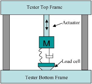
On an elastomer tester, the damper mass is excited by fixed displacement amplitude and the force response is measured at the base during a frequency sweep. Both the frequency at the peak of the force response and the frequency where the phase between the displacement and the force crosses 90° are identified as the natural frequency, but the phase crossing frequency is normally off a little bit from the amplitude peak due to the elastomeric damping. It is normally the frequency with maximum amplitude that is used as natural frequency.


Tuning the damper using electrical shakers is basically the same as using an elastomer tester. The shaker will shake the whole damper assembly for a frequency range. The accelerations on the damper base and mass are measured at the same time and the acceleration gain and phase are plotted. The frequency with maximum gain is considered as the natural frequency. In this case, either a large shaker must be available to shake the whole damper assembly, or a special fixture is needed to keep the assembly stable during the testing process.
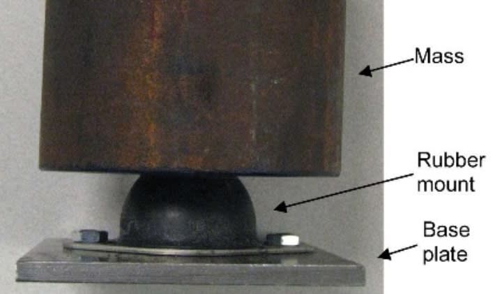
In tuning a damper via hammer impact testing, the method used in the case study presented here, with the damper base fixed to a rigid location, an impact force is applied on the mass using a modal hammer while the acceleration response is measured from the mass at the same time to get the frequency response function (FRF). The frequency where the mass is at its maximum A/F ratio or with 90° of phase angle is the damper’s natural frequency. As discussed above, the frequency at maximum FRF amplitude can be offset from the phase crossing frequency due to the damping.
Because rubber dynamic characteristics are dependent on excitation amplitudes, it is impossible to match exactly the excitation level of the damper on a machine structure by impacting it with a modal hammer. Hence, an in-situ tuning of the damper after it is installed on the structure can be done to either verify or fine-tune the damper.
Differences exist between the in-situ tuning and the previous damper tuning. First, the minimum vibratory response on the structure is required for in-situ tuning while maximum acceleration on the damper mass is wanted. Second, the excitation of the damper can be a real machine running condition or sledge hammer excitation of the machine structure.
During the in-situ tuning process, the damper was attached onto the cab roof and an accelerometer was put on the roof to measure the roof vibration. Compared with the original vibration on the roof, the roof vibration at the resonance was greatly reduced at 33 Hz, but two vibration peaks as expected showed up — one at a little higher frequency, the other at a little lower frequency.
Optimizing the TMD
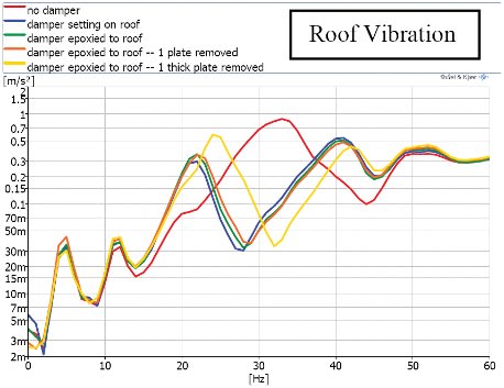
TMD effectiveness can be affected by the mass ratio, tuning frequency, damping, and its environment.
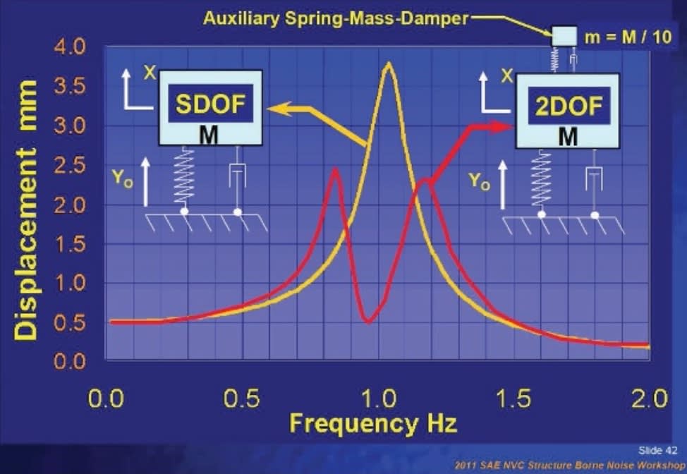
The damper mass ratio dominates the separation of the TDOF (two degrees of freedom) response peaks: in the effective damper range, a larger damper mass ratio will provide a better separation of the two response peaks that moves away from the original resonance peak.
Theoretically, a TMD should have exactly the same natural frequency as the base structure. In reality, both the base structure natural frequency and the damper’s can only be controlled to a certain tolerance. As a goal, the optimal damper frequency should be within 3% for its effectiveness.
The amount of damping of the TMD also plays a vital role. Generally speaking, increasing the damping will not only lower the TDOF responses peak amplitude (providing better attenuation over a wider frequency range), but also raise the response level in the “valley” between the two response peaks, degrading the attenuation of the base structure at its original resonance frequency.
The work demonstrated the basic performance of a TMD device designed for room temperature applications. For real-world applications, elastomers should be selected for the TMD design that have stable modulus and moderate damping levels as a function of temperature, and not be exposed to dramatic temperature variation such that the TMD will remain tuned and will provide stable attenuation performance with variations in temperature that will be encountered in the field.
This article is based on SAE International technical paper 2013-01-2010 by Jiantie Zhen, Aaron Brames, Tyler Williams, and Clinton Metzger of Caterpillar Inc.
More From SAE Media Group
Off-Highway Engineering
Fuel Cells for Auxiliary Power
Tech Briefs
New on the Market

Sensor Technology
Energy Harvesting Can Enable 1 Trillion Battery-Free Sensors in the IoT
Off-Highway Engineering
Israeli Startup REE Reinvents the Wheel with a Modular Approach to Future EV Design
Tech Briefs
Nanotransistors Stay Cool at High Voltages

Sensor Technology
What Will 5G Do for the IoT/IIoT?
Photonics & Imaging Technology
Photonic Communication Comes to Computer Chips
Off-Highway Engineering
Engine Developers Increase Efforts to Decrease Fuel Usage
Aerospace & Defense Tech Briefs
SAE International Extends Call for Abstracts, Seeks Submissions for AeroTech Conference
Automotive Engineering
Snapdragon Ride Flex Puts Safety, Infotainment onto Single Chip

Automotive Engineering
A Lesson in Multiphysics

Tech Briefs
SAE WCX Preview: Staying Ahead of the Curve
Electronics & Sensors INSIDER
Next-Gen Automotive Semiconductors Are Critical for Level 5 Driverless Cars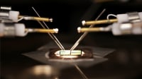
Off-Highway Engineering
Defending the Heavy-Vehicle Cyber Domain


Tech Briefs
Product of the Month

Tech Briefs
Turning Edible Fungi into Organic Memristors
Off-Highway Engineering
CV Autonomy: Picking the 'Low-Hanging Fruit'
Battery Technology
An Immersive Solution for Thermally Safer EV Batteries
Tech Briefs
Disrupting the Automobile Design Process
Aerospace & Defense Tech Briefs
The Future of Aircraft Electrification
Battery & Electrification Technology
EV Energy Management Powers Up

Top Stories
INSIDERManufacturing & Prototyping
![]() How Airbus is Using w-DED to 3D Print Larger Titanium Airplane Parts
How Airbus is Using w-DED to 3D Print Larger Titanium Airplane Parts
INSIDERManned Systems
![]() FAA to Replace Aging Network of Ground-Based Radars
FAA to Replace Aging Network of Ground-Based Radars
NewsTransportation
![]() CES 2026: Bosch is Ready to Bring AI to Your (Likely ICE-powered) Vehicle
CES 2026: Bosch is Ready to Bring AI to Your (Likely ICE-powered) Vehicle
NewsSoftware
![]() Accelerating Down the Road to Autonomy
Accelerating Down the Road to Autonomy
EditorialDesign
![]() DarkSky One Wants to Make the World a Darker Place
DarkSky One Wants to Make the World a Darker Place
INSIDERMaterials
![]() Can This Self-Healing Composite Make Airplane and Spacecraft Components Last...
Can This Self-Healing Composite Make Airplane and Spacecraft Components Last...
Webcasts
Defense
![]() How Sift's Unified Observability Platform Accelerates Drone Innovation
How Sift's Unified Observability Platform Accelerates Drone Innovation
Automotive
![]() E/E Architecture Redefined: Building Smarter, Safer, and Scalable...
E/E Architecture Redefined: Building Smarter, Safer, and Scalable...
Power
![]() Hydrogen Engines Are Heating Up for Heavy Duty
Hydrogen Engines Are Heating Up for Heavy Duty
Electronics & Computers
![]() Advantages of Smart Power Distribution Unit Design for Automotive...
Advantages of Smart Power Distribution Unit Design for Automotive...
Unmanned Systems
![]() Quiet, Please: NVH Improvement Opportunities in the Early Design...
Quiet, Please: NVH Improvement Opportunities in the Early Design...