


Solutions for RF Power Amplifier Test
As wireless mobile devices grow in capability and complexity, the associated growth in power demand is driving new approaches to battery utilization and power efficiency. One of the single largest power consumers in a wireless handset is the RF Power Amplifier (PA) and as such, improved efficiency techniques like Envelope Tracking (ET) and Digital Pre-Distortion (DPD) are being increasingly utilized. The key implication for test engineers — whether in design, characterization, or manufacturing test — is that testing these devices with this additional capability can potentially drive up both test cost and overall test time. This article discusses various approaches to maximizing test equipment utilization and reducing test times for such component RF PAs and front-end modules.
The Problem
 The demand for higher test speed spans from design validation to production test. As RF PAs support multiple modes, frequency ranges, and modulation formats, there is more to test during the validation phase. Thousands of tests are not uncommon. During RF PA production test, manufacturers have to deal with a number of critical issues; namely, speed, repeatability, cost, maintainability, and upgradability. Their biggest stress, however, comes from trying to balance speed and repeatability.
Typically, as test speed increases, repeatability decreases. Manufacturers must constantly struggle to balance these issues, while also keeping an eye on cost and maintainability. Addressing the speed challenge is further complicated by the fact that PAs are being manufactured in increasingly higher volumes to meet the demand for more and more wireless mobile devices, and have grown even more complex. Techniques like DPD and envelope tracking are often employed to help linearize the PA and increase its power efficiency, but these techniques only add to the testing that’s necessary during production, further slowing down the process. With PA manufacturers looking to reduce overall test times from 1.5 seconds to 500 ms or less, these slow-downs are simply no longer acceptable.
The Solution
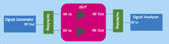
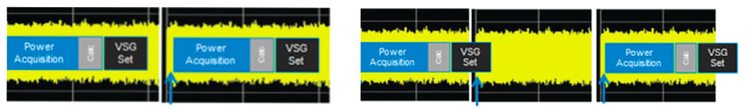
The first technique involves speeding up the PA power servo loop (Figure 1). A power servo loop is essentially a “test and adjust” process. The engineer sets the RF input power level to the Device-Under-Test (DUT), then checks the RF output of the DUT. If the RF output level is not within the required specification, the engineer changes the RF input level and checks again. This loop is continued until the correct output power level is achieved. Then, and only then, can the engineer start making measurements on the DUT. Getting this process done fast and allowing the engineer to quickly move on to making measurements is a key way to speed the overall RF PA test time.
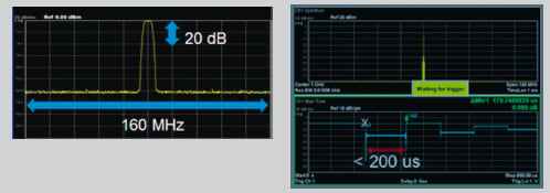
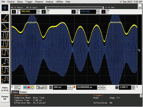
The recommended PXI VSG approach for the power servo loop is to set the RF power level to the maximum level required from the source, then use the baseband power level to adjust the power level to the required input level. This is an iterative process that is performed until the output power reaches the required level for testing. The method is fast and accurate, enabling power servos to converge very quickly. In fact, with this baseband tuning technology, amplitude changes of up to 20 dB can be achieved in less than 200 μs (Figure 2). It can also be used for frequency offsets within the bandwidth of the generator, making it especially useful for measuring multiple channels within a band.
Fast Signal Processing
Once the power level is set correctly, the need for speed and accuracy switches to the analysis hardware. In this case, a PXIe Vector Signal Analyzer (VSA), which operates from 1 MHz to 6 GHz, or a PXIe performance VSA, which operates from 9 kHz to 27 GHz – both with up to 160MHz analysis bandwidth – offer the ideal solution. With outstanding linearity, repeatability, and absolute amplitude accuracy, power servos can converge faster, thereby reducing PA component test times. Moreover, the PXI VSA can be combined with the PXI VSG for a fast, compact PA test solution.
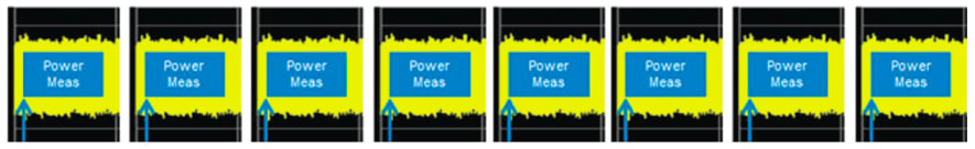
- Power Acquisition for Servo and ACPR. This method produces fast results by using the same power acquisition mode for both the servo and ACPR measurement. First, it’s used for the servo loop, which normally converges between 2 and 3 steps. Once it converges, the input power and gain are measured. Next, the ACPR is measured. This is performed 4 to 6 times to measure the 2 or 3 adjacent channels.
- Power Acquisition for Servo, FFT for ACPR. With this approach, the servo loop uses the power acquisition mode as above, but the FFT mode is used for power measurements. The engineer simply makes one FFT measurement instead of 4 to 6, and from that, calculates the power for all adjacent channels. The method enables faster measurements by simply reducing the number of measurements needed to obtain the ACPR data.
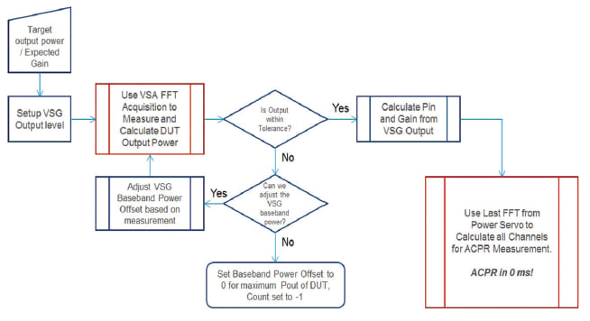
- FFT Acquisition for Servo and ACPR. With this approach, the FFT acquisition mode is used for both the servo and ACPR and because of this, when it comes to making power measurements, no further measurement for ACPR is required. With no ACPR measurement necessary, this approach is by far the fastest of the three options (Figure 3).
Optimizing Repeatability and Test Time
Another option is to use an external trigger to start the measurement. In this case, repeatability improves because the engineer is always measuring at the same time within the waveform, and there is no variation in modulation signal during the measurement. Unfortunately, repeatability comes at the expense of measurement time. Only one point in the waveform can be measured at any given time, and the delay to wait for an external trigger is, on average, half the total time of the waveform. Since the engineer isn’t actually making measurements during most of the waveform, this is wasted time.
While this method works well for constant signals like WCDMA and LTE-FDD, it does not work for bursted waveforms (e.g., GSM and LTE-TDD). For these measurements, the engineer must maintain the duty cycle. Measurement time is improved by adjusting the burst length to be slightly longer than the acquisition time. The off time is then used for calculations and the PXI VSG setting.
Implications of Emerging Technologies

A typical characterization and test solution for testing PAs with ET and DPD is shown in Figure 6. The solution includes waveform generation software and PA test software for ET and DPD. It also includes hardware required for RF signal generation, envelope waveform generation, DUT, power, and RFFE control.
Summary
Reducing validation or manufacturing test time while maintaining repeatability, especially in the face of emerging technologies like ET and DPD, is absolutely essential to PA manufacturers. Fortunately, this can be accomplished through a combination of real-time signal processing, innovative baseband tuning technology, FFT acquisitions for power servo and ACPR measurements, and use of shorter waveforms with an external trigger.
This article was written by Jan R. Whitacre, Mainstream Wireless Technology Lead, Global Programs Marketing, for Keysight Technologies, Santa Rosa, CA. For more information, Click Here .
More From SAE Media Group
Aerospace & Defense Tech Briefs
New Pulse Analysis Techniques for Radar and EW
Aerospace & Defense Tech Briefs
Pulse Analysis Techniques for Radar and Electronic Warfare
Aerospace & Defense Tech Briefs
Enhance EMC Testing with Digital IF
Aerospace & Defense Tech Briefs
Using High Bandwidth Oscilloscopes to Analyze Radar and Electronic Warfare Systems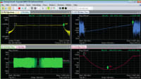
Aerospace & Defense Tech Briefs
Combining Software and Hardware for Highly Specialized Multichannel Spectrum Monitoring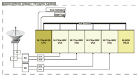
Aerospace & Defense Tech Briefs
90° Hybrid Coupled Power Amplifier – Pros and Cons
Aerospace & Defense Tech Briefs
NeXtRAD SDR Interface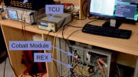
Tech Briefs
Test Strategies to Track Hypersonic Threats
Aerospace & Defense Tech Briefs
System Generates and Simulates Skin-Echo Pulses for Radar Testing

Aerospace & Defense Tech Briefs
Tracking WiFi Signals to Passively See Through Walls
Aerospace & Defense Tech Briefs
Mil-Aero Design Embraces Intelligent Application-Ready ATCA Platforms
Aerospace & Defense Tech Briefs
Enhancing Mission Readiness with Rugged Portable Instruments
Aerospace & Defense Tech Briefs
Software-Designed System Improves Wireless Test Speed and Coverage
Aerospace & Defense Tech Briefs
Validation of Ubiquitous 2D Radar
Aerospace & Defense Tech Briefs
Development of a 94 GHz Radar System for Dedicated Bird Detection at Airports and Airfields
Aerospace & Defense Tech Briefs
Using Ruggedized Test Equipment to Solve Jet Engine Problems
Aerospace & Defense Tech Briefs
Compact Power Amplifier Solution for Electronic Warfare
Aerospace & Defense Tech Briefs
Creating a Synthetic Virtual Instrument for Avionics Testing
Aerospace & Defense Tech Briefs
New RF Strategies for Software Radio
Aerospace & Defense Tech Briefs
What is Pulse Shaping?
Aerospace & Defense Tech Briefs
An Integrated Framework for Complex Radar System Design
Aerospace & Defense Tech Briefs
RF FPGAs for Multi-Function Systems
Aerospace & Defense Tech Briefs
Unmanned Ground Vehicle Communications Relays
Aerospace & Defense Tech Briefs
Solid-State Microwave Power Module
Aerospace & Defense Tech Briefs
Broadband 1.2- and 2.4-mm Gallium Nitride (GaN) Power Amplifier Designs
Aerospace & Defense Tech Briefs
New Products
Aerospace & Defense Tech Briefs
Microwave Photonic Notch Filter
Aerospace & Defense Tech Briefs
How to Specify and Select RF Filters

Top Stories
INSIDERManufacturing & Prototyping
![]() How Airbus is Using w-DED to 3D Print Larger Titanium Airplane Parts
How Airbus is Using w-DED to 3D Print Larger Titanium Airplane Parts
INSIDERManned Systems
![]() FAA to Replace Aging Network of Ground-Based Radars
FAA to Replace Aging Network of Ground-Based Radars
NewsTransportation
![]() CES 2026: Bosch is Ready to Bring AI to Your (Likely ICE-powered) Vehicle
CES 2026: Bosch is Ready to Bring AI to Your (Likely ICE-powered) Vehicle
NewsSoftware
![]() Accelerating Down the Road to Autonomy
Accelerating Down the Road to Autonomy
EditorialDesign
![]() DarkSky One Wants to Make the World a Darker Place
DarkSky One Wants to Make the World a Darker Place
INSIDERMaterials
![]() Can This Self-Healing Composite Make Airplane and Spacecraft Components Last...
Can This Self-Healing Composite Make Airplane and Spacecraft Components Last...
Webcasts
Defense
![]() How Sift's Unified Observability Platform Accelerates Drone Innovation
How Sift's Unified Observability Platform Accelerates Drone Innovation
Automotive
![]() E/E Architecture Redefined: Building Smarter, Safer, and Scalable...
E/E Architecture Redefined: Building Smarter, Safer, and Scalable...
Power
![]() Hydrogen Engines Are Heating Up for Heavy Duty
Hydrogen Engines Are Heating Up for Heavy Duty
Electronics & Computers
![]() Advantages of Smart Power Distribution Unit Design for Automotive...
Advantages of Smart Power Distribution Unit Design for Automotive...
Unmanned Systems
![]() Quiet, Please: NVH Improvement Opportunities in the Early Design...
Quiet, Please: NVH Improvement Opportunities in the Early Design...