


Measuring and Accounting for Suspension
TARDEC teamed with SEA Ltd. to develop a system to measure the suspension parameters, center of gravity, and moments of inertia of wheeled vehicles in the never ending quest to model and predict vehicle dynamic behavior.

The U.S. Army Tank Automotive Research, Development, and Engineering Center (TARDEC) contracted Scientific Expert Analysis Limited (SEA) to build a vehicle suspension parameter testing machine that would enable it to study the dynamics of military wheeled vehicles. The machine, named the Suspension Parameter Identification and Evaluation Rig (SPIdER) by the Army, is installed in TARDEC’s facility in Warren, MI. The SPIdER is a companion to the VIPER (Vehicle Inertia Parameter Evaluation Rig), also designed by SEA and installed in Warren.
TARDEC depends upon such facilities to assist engineers in their ongoing efforts to model and predict vehicle dynamic behavior, so as to build vehicles that are less prone to roll over, have better handling stability, and perform better in rough terrain. SPIdER measures quasistatic steering and suspension properties and tire vertical static stiffness, and is not intended to be used for durability or strength testing.
In the past there have been few attempts to build suspension testing machines for large vehicles. Much of the former and earliest work on heavy truck suspension parameter measurements has been done by the University of Michigan Transportation Research Institute. That facility grounds the vehicle body similar to the SPIdER, but can measure only one axle at a time. More recently, Michelin has designed and built a suspension measurement facility for heavy trucks.
Designing a SPIdER
The SPIdER can accommodate vehicles with track widths up to 110 in. The maximum allowed vertical motion (jounce) from the drive-on position is ±11.5 in and maximum roll angle that can be attained is ±5°.
The machine operates by holding the body of the vehicle stationary while the wheels are moved under the vehicle. The machine is installed on a heavy, steel, T-slotted bed plate, and a variety of restraint components (chains, custom brackets, fixtures, and jacks) are used to nominally fix the body of the vehicle to the bed plate. Restraints are designed to attach and secure a variety of different vehicle sizes and loading conditions. Sprung mass is fixed and any minimal sprung mass motions of up to tenths of an inch are directly measured and accounted for in the calculations.
If measured sprung mass experiences more than tenth of an inch motion, additional restraining will be set up. The vehicle body (sprung mass) is not assumed to be rigid; rather, vertical motion measurements are taken at two locations for each wheel being tested. These measurements of the body position relative to ground are made just ahead of and just behind the wheel location being tested, and a linear interpolation is made to estimate the motion of the vehicle body directly above the wheel being tested. A total of eight string potentiometers are used for these measurements.
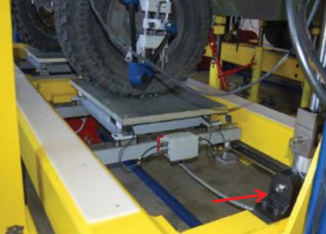
Up to two axles at a time can be tested; however, a single axle can also be tested. Tandem linked axles, when present, are typically tested together. For each axle there is an axle frame that supports the main test hardware. At the end of each axle frame is a vertical hydraulic cylinder. The bottom of the cylinder, the rod end, is attached to the axle frame, and a pylon attached to the T-bed supports the stationary top of the cylinder.

Each axle frame holds a wheel pad for the left and right wheels. Each wheel pad is capable of supporting very wide sets of dual tires. Each wheel pad is free to float in the longitudinal (SAE XT) and lateral (SAE YT) directions on linear rails with ball bearings. The effective coefficient of friction of these rails is on the order of 0.002. Steer motion of the wheel pad is allowed by a large crossed roller bearing under the wheel pad. This bearing can support a load significantly offset from the centerline of the bearing, so the tire need not be perfectly centered.
Directly under the tire is a heavy steel top plate. Under the top plate is the crossed roller bearing that allows steer. Under the bearing is a heavy steel plate supported by four load cells. Using four cells allows for the calculation of not only the total load on the wheel but also the center of pressure of that load.
For single tires the center of pressure is essentially in the center of the contact patch, but for dual tires it is not necessarily in the geometric center of the contact patches. Not only can dual tires have different inflation pressures, but during the roll tests the dual tires will typically not have the same load.
To directly measure changes in track width the lateral location of the wheel pad is also measured, using a linear potentiometer. Longitudinal motion of the vehicle body is measured with a string potentiometer in one location, on the vehicle centerline.
Although they can be operated individually, the normal modes of operation for the hydraulic cylinders (four for the total machine) are to move equally during a bounce test, or equal and opposite during a roll test.
During the bounce test the axle frames and wheel pads move strictly vertically, while during the roll test the axle frames and wheel pads are forced to rotate about a longitudinal line in the plane defined by the top surfaces of the wheel pads, which is the ground (road) plane, halfway between the left and right wheels.
Each axle frame has heavy steel ears protruding from the left and right sides that ride in a vertical groove. These ears and grooves prevent the axle frame from rotating about the vertical yaw axis and lateral pitch axis while allowing it to rotate only about the longitudinal roll axis. The ears also prevent longitudinal and lateral motion, while allowing vertical motion. Together, the ears, grooves, and cylinders limit the motion of the axle frame without overconstraining it. It is therefore impossible to bind the axle frame, even if the cylinders are not synchronized.
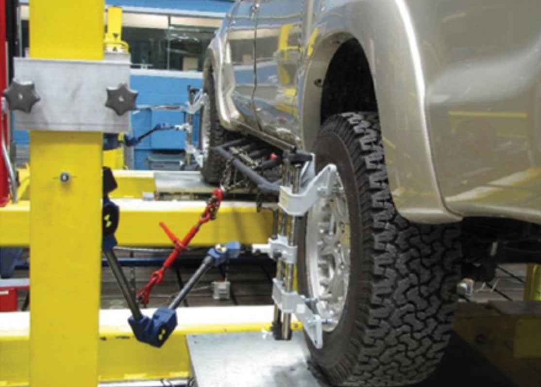
The motions of the wheel center relative to the ground, along with the wheel loads, constitute the most important measurements on the entire machine. The five wheel measurements: x-motion, y-motion, z-motion, and the steer and camber angles are taken together using a coordinate measuring machine attached to each wheel. The stylus of this device is mounted co-linearly with the spin axis of the wheel, and the distance from the tip of the stylus to the center plane of the tire is measured. Thus, the 5° of motion of the wheel center can be calculated.
The base of the coordinate measuring machine is mounted to a stand that does not move during the test. During the test setup, once the base of the coordinate measuring machine is fixed, a calibration fixture is used to “teach” the machine the orientation, zero positions, angles of the x-, y-, and z-axes, and also the location of the z=0 plane (the ground plane). This allows for the true steer and camber angles to be measured.
During the bounce and roll tests the hand-wheel in the cab is locked by attaching suction cups to the windshield and then attaching rods between the suction cups and the hand-wheel. Although the hand-wheel is effectively locked, the hand-wheel angle is recorded so that any hand-wheel motion can be compensated for in the road-wheel angle.
For the steer ratio test the same CMM is used to measure the steer angles of the wheels. Inside the cab of the vehicle the hand-wheel is unlocked and a rotary encoder is used to measure the angle of the hand-wheel, as an operator manually turns the hand-wheel through a specified range of motion.
Typically, the hand-wheel is rotated through its full range of motion (lock to lock); however, a smaller range can be used. This test is typically done with the engine and power steering turned on. Steering resistance is minimal, as the road wheels are free to steer on the crossed roller bearings.
Controlling a SPIdER
The only controlled motion during the bounce and roll tests is that of the four hydraulic cylinders. Each cylinder, controlled by individual servo valves, has a linear potentiometer attached directly to it. The maximum flow in either extension or retraction is controlled by pressure compensated flow control valves (two valves per cylinder) that essentially set the nominal speed of the cylinder.
While the servo valves could be used to input complex motion and speed profiles, they are used primarily to provide a constant displacement rate that is controlled by the flow control valves. Measurements are taken continuously at 0.1 s intervals. By matching the flow rates of all the flow control valves, all cylinders arrive at each stopping point at about the same time. Final stopping position is controlled to within about ±0.02 in.
Once the test is set up, the entire test sequence is run automatically following operator initiation. The computer controls the motion and determines when the motion should reverse, based on several criteria.
For a bounce test, the wheel pads (entire axle frame unit) move down a short distance, then move back up to the starting point before the first measurements are taken. Then the wheel pads move up to the point of maximum suspension compression, recording data continuously.
Typically, the reversing point is when an operator-specified maximum axle load or maximum suspension displacement is reached. The wheel pads move down until the suspension extension reaches a point when the loads on the wheel pads reach the operator-specified minimum value.
Finally, the wheel pad motion is reversed to the up direction until the original zero position is reached. Each axle has its own stopping point for suspension compression and extension limits, based on the operator-specified test limits. There are numerous internal checks (full e-stop of the system, rest position, full monitoring of the minimum load on the wheel pad, maximum longitudinal movement of the sprung mass) in place to protect both the SPIdER and the vehicle.
For a roll test, one end of the axle frame unit moves up while the other end moves down an equal amount. The frame units are rolled to an operator-specified angle, and then reversed to roll to the equal and opposite. Finally, the frame units are rolled back to their original zero position.
Bounce, roll, and steering ratio tests
Currently the SPIdER is capable of doing three types of quasi-static tests: bounce, roll, and steering ratio tests. During each of these tests over 70 transducers are used to monitor displacements, angles, forces, and pressures. Some of these signals are used to control the SPIdER frame motions and check for test and safety limits. However, the majority of the transducer signals are used to compute the engineering quantities of interest.
During a bounce test, the axle or axles are moved vertically 60 while the vehicle body is held stationary. Vertical forces at the tires, the wheel location in three dimensions, the road-wheel steer and camber angles, and the slight vertical deflections of the body are measured. The vertical motion of the wheel pad is not measured directly but is calculated from the known hydraulic cylinder motions and the estimated machine deflection. The frames under the wheel pads are very stiff, but may deflect a few tenths of an inch under maximum load.
In the roll test, the maximum possible roll angle is 5°. When a single wheel load goes to 10% of its initial value the motion automatically reverses, as loss of wheel contact is very undesirable, especially when the axle frames and wheel pads are tilted at a large angle. Generally, the roll test produces lower forces than the bounce test. With the ability to measure the center of pressure on the wheel pad, roll stiffness is accurately measured even for wide sets of dual tires.
In order to simulate rolling with differing load conditions, it is possible to give some initial compression or extension to the suspension and then perform the roll test. The rolling always occurs about an axis in the ground plane, which is the plane of the tops of the wheel pads.
Suspension bounce and roll stiffness characteristic curves typically have a hysteresis loop, especially if the suspension contains leaf or pneumatic springs. At the slow speeds used for these tests, the sizes of these loops provide a measure of coulomb and (low speed) viscous damping in the springs, suspension bushings, and other parts of the suspension system.
This article is based on SAE International technical paper 2015-01-2751, doi:10.4271/2015-01-2751, by Baseski, I., Norman, K., Ryan, D., and Stahara, S., TARDEC.
More From SAE Media Group
Automotive Engineering
Wheel Motion Sensor
Off-Highway Engineering
Engineering the World’s Fastest Tractor
Automotive Engineering
Suspension Parameter Measuring Machine
Off-Highway Engineering
REE’s P7 Brings Advanced Suspension Control to Medium-Duty Trucks
NASA Spinoff
Shuttle Tire Sensors Warn Drivers of Flat Tires
Motion Design INSIDER
NIST is Calibrating Gear Artifacts

Sensor Technology
Measurement Technology Drives Vehicle Development Forward

Off-Highway Engineering
Modern Approaches to Electric Vehicle Noise and Vibration
Tech Briefs
Charging into the Future with EV Battery Testing
Motion Design
Multi-Axis Motion Controller Accelerates Gear Testing
Automotive Engineering
Soft Tests for Autonomous Vehicles
Motion Design
Built-In Vibration Control to Soundproof Spaces
Motion Design INSIDER
Autonomous Bus Sounds: It’s All About When, Not How
Battery & Electrification Technology
Advancing Higher Speeds and New Techniques for EV Recharging
Off-Highway Engineering
Allison Builds a Testing Powerhouse


Motion Design INSIDER
Computer Simulation Accurately Models Moving Cars

Automotive Engineering
Expanding the ‘Bubble’ of Cabin Acoustics
Battery & Electrification Technology
Overcoming Challenges and Boosting Productivity for EV Battery and E-Axle Testing
Automotive Engineering
FEV and the Art of EV Testing
Automotive Engineering
Xtrac Reveals 2014 Formula One Gearbox Technology
Autonomous Vehicle Engineering
GM Announces Door-To-Door Ultra Cruise ADAS

Off-Highway Engineering
Arctic Autonomy

Top Stories
INSIDERManufacturing & Prototyping
![]() How Airbus is Using w-DED to 3D Print Larger Titanium Airplane Parts
How Airbus is Using w-DED to 3D Print Larger Titanium Airplane Parts
INSIDERManned Systems
![]() FAA to Replace Aging Network of Ground-Based Radars
FAA to Replace Aging Network of Ground-Based Radars
NewsTransportation
![]() CES 2026: Bosch is Ready to Bring AI to Your (Likely ICE-powered) Vehicle
CES 2026: Bosch is Ready to Bring AI to Your (Likely ICE-powered) Vehicle
NewsSoftware
![]() Accelerating Down the Road to Autonomy
Accelerating Down the Road to Autonomy
EditorialDesign
![]() DarkSky One Wants to Make the World a Darker Place
DarkSky One Wants to Make the World a Darker Place
INSIDERMaterials
![]() Can This Self-Healing Composite Make Airplane and Spacecraft Components Last...
Can This Self-Healing Composite Make Airplane and Spacecraft Components Last...
Webcasts
Defense
![]() How Sift's Unified Observability Platform Accelerates Drone Innovation
How Sift's Unified Observability Platform Accelerates Drone Innovation
Automotive
![]() E/E Architecture Redefined: Building Smarter, Safer, and Scalable...
E/E Architecture Redefined: Building Smarter, Safer, and Scalable...
Power
![]() Hydrogen Engines Are Heating Up for Heavy Duty
Hydrogen Engines Are Heating Up for Heavy Duty
Electronics & Computers
![]() Advantages of Smart Power Distribution Unit Design for Automotive...
Advantages of Smart Power Distribution Unit Design for Automotive...
Unmanned Systems
![]() Quiet, Please: NVH Improvement Opportunities in the Early Design...
Quiet, Please: NVH Improvement Opportunities in the Early Design...